
Every electronics project begins with a fundamental manufacturing decision: how will components attach to the printed circuit board? For more than four decades, the industry has debated the merits of surface mount technology against traditional through-hole construction. In 2026, both methods remain relevant, but their optimal applications have shifted as component packages shrink, power requirements evolve, and reliability standards tighten. Understanding when through-hole PCB assembly outperforms SMT — and vice versa — can save engineering teams months of redesign, thousands of dollars in tooling, and countless hours of field troubleshooting. This comparison guide breaks down the technical differences, cost implications, and real-world use cases for each technology, so you can specify the right approach before your first prototype leaves the PCB assembly manufacturer.
Keep Best PCB Assembly Co., Ltd has operated SMT and through-hole lines since 2012 across facilities in Shenzhen, Jiangmen, and Thailand. The company processes everything from miniature IoT sensors built entirely with 01005 passives to industrial motor controllers that rely on heavy through-hole capacitors and connectors. That dual-capability perspective informs the framework below.
What Is SMT PCB Assembly?
Surface mount technology places components directly onto pads on the surface of the PCB, then solders them in place using reflow ovens. No holes are drilled for component leads. Instead, flat metalized terminations on the underside or sides of the package make electrical and mechanical connection to the board. SMT PCB assembly dominates consumer electronics because it supports extreme miniaturization, automated high-speed placement, and double-sided component loading.
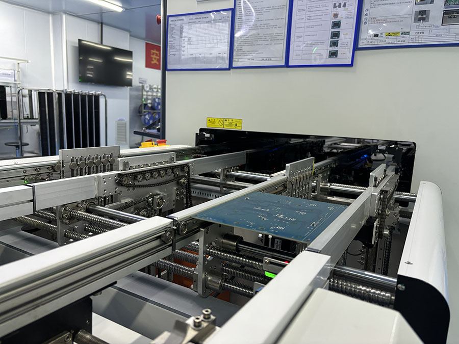
Modern SMT placement machines can position components at rates exceeding 80,000 components per hour with placement accuracy below 35 micrometers. Passive packages have shrunk from 1206 to 0603, 0402, 0201, and now 01005 metric, enabling incredible density in smartphones, wearables, and medical implants. Integrated circuit packages range from simple SOPs and QFPs to complex BGAs, QFNs, and chip-scale packages where solder joints are entirely hidden beneath the device.
Advantages of SMT PCB assembly
- Higher component density — Components mount on both sides of the board, maximizing space efficiency.
- Faster automated assembly — Pick-and-place machines handle SMT components at speeds impossible for manual insertion.
- Lower per-unit labor cost — Minimal human intervention reduces assembly time and cost at volume.
- Smaller board size — Compact designs reduce material cost and enable portable product form factors.
- Better high-frequency performance — Shorter lead lengths reduce parasitic inductance and capacitance.
Limitations of SMT PCB assembly
- Lower mechanical strength — Surface-mounted components can detach under vibration, shock, or thermal cycling stress.
- Difficult manual prototyping — Hand-soldering fine-pitch QFNs and BGAs requires skill and specialized equipment.
- Higher initial tooling cost — Stencils, precise reflow profiles, and AOI inspection add upfront investment.
- Challenging field repair — Rework on hidden solder joints demands hot-air stations and X-ray verification.
What Is Through-Hole PCB Assembly?
Through-hole technology inserts component leads through drilled holes in the PCB, then solders them on the opposite side using wave soldering or selective soldering equipment. The leads extend completely through the board thickness, creating a mechanical anchor that is far stronger than surface-mount adhesion. Through-hole PCB assembly remains the preferred method for components that must withstand significant physical stress, high current, or repeated mechanical engagement.
Common through-hole components include electrolytic capacitors, power transistors, transformers, relays, large connectors, and any device where the user interacts directly with the component — such as switches, potentiometers, and header pins. The leads themselves act as thermal pathways, helping dissipate heat from power semiconductors into the board and surrounding copper planes. For engineers working on power electronics or ruggedized equipment, through-hole PCB assembly offers reliability advantages that SMT simply cannot match.
Advantages of through-hole PCB assembly
- Superior mechanical reliability — Leads passing through the board create robust joints resistant to vibration and shock.
- Excellent thermal management — Component leads conduct heat into internal copper layers and the opposite board side.
- Higher current capacity — Thicker component leads and larger solder fillets handle greater current loads.
- Easier manual prototyping and repair — Standard soldering irons and desoldering tools work effectively.
- Better for user-accessible interfaces — Connectors, switches, and controls benefit from the physical strength of through-hole mounting.
Limitations of through-hole PCB assembly
- Larger board footprint — Drilled holes and lead spacing consume significantly more area than surface-mount equivalents.
- Higher labor cost — Component insertion often requires manual or semi-automated equipment, slowing throughput.
- Single-sided component placement — Through-hole parts generally occupy space on both sides, limiting density.
- Slower assembly speed — Wave soldering cycles are longer than reflow, and selective soldering adds processing time.
Head-to-Head Technical Comparison
| Attribute | SMT PCB Assembly | Through-Hole PCB Assembly |
|---|---|---|
| Component density | Very high (double-sided) | Low to moderate |
| Mechanical strength | Moderate (adhesion only) | Very high (mechanical anchor) |
| Assembly speed | Very fast (automated) | Slower (manual or semi-auto) |
| Prototyping ease | Difficult for fine pitch | Easy with standard tools |
| High-frequency performance | Excellent | Good (longer leads) |
| Power / current handling | Limited by package size | Excellent (large leads) |
| Repairability | Requires specialized rework | Easy manual repair |
| Cost at low volume | Higher (stencil, setup) | Lower (minimal setup) |
| Cost at high volume | Lower (fast automation) | Higher (labor intensive) |
The table above illustrates why the question is not which technology is better, but which technology is better for a specific application. A medical implant demands the miniaturization of SMT. A mining power supply demands the mechanical ruggedness of through-hole PCB assembly. Most products fall somewhere between these extremes, which is why many boards today use both methods strategically.
When SMT Is the Clear Winner
SMT PCB assembly should be your default choice when the product requires compact size, high-speed signal integrity, or mass production economics. Smartphones, tablets, wearable fitness trackers, wireless earbuds, and IoT sensors are almost exclusively surface-mount because no alternative achieves the required density. RF circuits, high-speed digital buses, and DDR memory interfaces also benefit from the reduced parasitic inductance of short SMT interconnections.
If your design uses components smaller than 1206, includes BGAs or QFNs, or requires double-sided loading, SMT is not merely preferred — it is mandatory. Attempting to implement these designs with through-hole components would result in boards ten times larger and at costs that make the product uncompetitive. In these scenarios, through-hole PCB assembly has no practical role except perhaps for external connectors.
When Through-Hole Assembly Still Dominates
Through-hole PCB assembly remains indispensable in environments where mechanical stress, thermal cycling, or high current would compromise surface-mount joints. Automotive engine controllers, aerospace avionics, industrial motor drives, heavy-duty power supplies, and outdoor telecommunications equipment all rely on through-hole components for their most critical connections. The mechanical anchor created by leads passing through the board provides a safety margin that surface-mount joints cannot replicate.
Connectors that users plug and unplug repeatedly — USB ports, Ethernet jacks, power inlets, terminal blocks — almost always use through-hole mounting because the mechanical load would tear surface-mount pads off the board. Large electrolytic capacitors in power supplies use through-hole leads both for current capacity and because their weight makes surface-mount attachment unreliable over years of thermal cycling. For any product destined for harsh environments — military, oil and gas, agriculture, and transportation — through-hole PCB assembly frequently remains the specified method for all components above a certain size threshold.
Hybrid PCB Assembly: The Best of Both Worlds
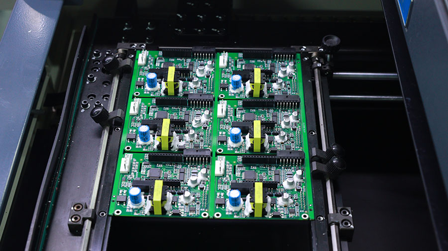
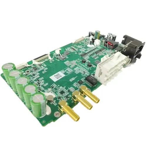
The majority of modern electronics use both technologies on the same board. A typical industrial controller might have SMT microcontrollers, resistors, and ICs on the top side, with through-hole power devices, connectors, and large capacitors securing the board to a metal chassis. This hybrid approach optimizes cost, size, and reliability by assigning each component to the attachment method best suited to its function.
Hybrid assembly does add process complexity. The board typically undergoes SMT reflow first, then through-hole insertion and wave or selective soldering afterward. Careful design-for-manufacturing review ensures that SMT components on the bottom side survive the wave soldering process, or are masked during selective soldering. A capable one-stop PCBA solution provider will flag these interactions during DFM analysis and recommend process sequences that protect already-mounted components.
Keep Best PCB Assembly processes hybrid boards daily across its SMT and DIP lines. The MES traceability system tracks each component by its attachment method, so quality data can be segmented by process type during root-cause analysis. Whether your project requires pure SMT, pure through-hole PCB assembly, or a carefully orchestrated hybrid build, the production planning team can validate feasibility before the first component is placed.
Cost, Speed, and Quality Trade-offs
Beyond the technical characteristics, the business implications of choosing SMT versus through-hole are significant. For quick turn PCB assembly prototypes, through-hole can actually be faster because it avoids stencil fabrication and reflow profile development. A small batch of through-hole PCB assembly prototypes can be hand-assembled and soldered in hours, while SMT prototypes require stencil cutting, machine programming, and process verification.
At volume, the economics invert. An automated SMT line placing 50,000 components per hour delivers unit costs that manual through-hole insertion cannot approach. The break-even point varies by product complexity but typically falls between 100 and 500 units for designs that are fully compatible with SMT automation. Products that genuinely require through-hole PCB assembly for reliability reasons accept the higher labor cost as a necessary investment in field performance.
Quality considerations also differ. SMT defects such as tombstoning, insufficient solder, and bridging are best caught with SPI and AOI systems. Through-hole defects such as insufficient fill, blowholes, and lifted pads require different inspection criteria, often verified with X-ray on thick boards or destructive cross-section analysis for high-reliability applications. A PCB assembly manufacturer with both capabilities can apply the right inspection regime to each technology, ensuring that neither SMT nor through-hole PCB assembly leaves the factory with latent quality risks.
How to Specify the Right Technology for Your Project
The decision framework is straightforward when you answer four questions honestly:
- What is the operating environment? Vibration, shock, and thermal cycling favor through-hole PCB assembly. Controlled indoor environments favor SMT.
- What is the expected production volume? Low volumes and frequent design changes favor through-hole or manual SMT. High volumes favor fully automated SMT.
- What are the size constraints? Portable consumer products demand SMT density. Rack-mounted industrial equipment has space for larger through-hole components.
- What is the product lifespan and service model? Disposable electronics use SMT. Repairable industrial equipment with 10-20 year lifespans benefits from through-hole PCB assembly serviceability.
Most experienced design teams do not choose one technology exclusively. They map each component in the BOM to the optimal attachment method, then work with their contract electronics manufacturer to verify that the resulting process sequence is manufacturable, testable, and cost-effective. A thorough DFM review will identify whether hybrid assembly is required and will flag components that create process conflicts.
Conclusion
Neither SMT nor through-hole PCB assembly has become obsolete. Each technology has carved out a permanent role in electronics manufacturing based on undeniable physical and economic advantages. SMT wins on density, speed, and high-frequency performance. Through-hole PCB assembly wins on mechanical strength, thermal management, and serviceability. The smartest engineering teams do not treat this as an either-or choice — they design hybrid assemblies that combine both methods strategically.
If you are evaluating manufacturing options for an upcoming project, start the conversation early. DFM feedback at the schematic stage prevents costly redesigns later. Keep Best PCB Assembly offers get a free quote consultations that include technology recommendations based on your specific BOM, volume forecasts, and reliability requirements. With ISO 9001, ISO 13485, and IATF 16949 certifications across facilities in China and Thailand, the company delivers both SMT and through-hole PCB assembly with the quality systems and traceability that modern electronics demand.
