
Surface mount technology transformed electronics manufacturing when it displaced through-hole assembly as the dominant production method. Today, SMT assembly accounts for the vast majority of components placed on printed circuit boards, enabling the miniaturization, automation, and cost efficiency that define modern electronics.
This guide provides a comprehensive overview of SMT assembly, from fundamental concepts to advanced process control. Whether you are new to electronics manufacturing or seeking to deepen your understanding, this resource covers the essential knowledge every engineer and buyer should possess.

What Is Surface Mount Technology?
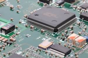
Surface mount technology is a method of assembling electronic circuits where components are mounted directly onto the surface of a printed circuit board, rather than having their leads inserted through holes in the board. SMT components, also called surface mount devices, have small metal tabs or terminations that are soldered to copper pads on the PCB surface.
The key advantage of SMT over through-hole technology is component density. Because SMT components are smaller and can be placed on both sides of the board, a given PCB area can accommodate many more components. This density advantage has enabled everything from smartphones to medical implants, which would be physically impossible to build with through-hole components.
Additional advantages include better high-frequency performance due to shorter lead lengths and reduced parasitic effects, lower cost per component placement in automated assembly, and improved mechanical performance under shock and vibration since components have lower mass and a lower profile.
The SMT Assembly Process: Step by Step
Step 1: Solder Paste Printing
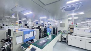
The SMT process begins with applying solder paste to the PCB. A stainless steel stencil, laser-cut with openings corresponding to every component pad on the board, is aligned over the PCB. Solder paste, a mixture of tiny solder spheres suspended in flux, is spread across the stencil using a squeegee blade. The paste deposits through the stencil openings onto the pads below.
Solder paste printing is widely considered the most critical step in SMT assembly. Industry studies consistently show that 50 to 70 percent of SMT assembly defects originate at the solder paste printing stage. Insufficient paste, excess paste, smearing, and misalignment all create downstream soldering defects that become progressively more expensive to correct at later stages.
Modern SMT lines use solder paste inspection machines immediately after printing. These 3D optical systems measure paste volume, height, area, and positional accuracy for every deposit on the board. Boards that fail SPI criteria are cleaned and reprinted before components are placed, preventing defects from propagating downstream.
Step 2: Component Placement
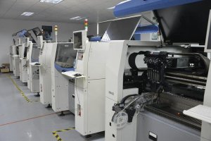
After paste inspection, the board enters the pick-and-place machine. These high-speed robotic systems pick components from tape reels, trays, or tubes using vacuum nozzles and place them onto the corresponding paste deposits. Modern placement machines achieve placement rates of 20,000 to over 100,000 components per hour, depending on the machine category and component mix.
Component placement accuracy is measured in microns. For standard chip components like 0603 or 0402 resistors, placement accuracy of 50 microns is acceptable. For fine-pitch ICs and BGAs, accuracy requirements tighten to 25 microns or less. The placement machine’s vision system measures each component before placement and adjusts position to compensate for any deviation from nominal dimensions.
Feeder setup and verification are critical for placement quality. Loading the wrong component into a feeder position creates defects that are difficult to detect until functional test. Advanced placement systems use intelligent feeders with RFID or barcode verification, confirming that the correct component is loaded in the expected feeder position before production begins.
Step 3: Reflow Soldering
After all components are placed, the board passes through a reflow oven. The oven has multiple heating zones that raise the board temperature through a precisely controlled profile. The profile typically includes a preheat stage to activate the flux and drive off solvents, a soak stage to equalize temperatures across the board, a reflow stage where the temperature peaks above the solder melting point, and a cooling stage where the solder solidifies.
The reflow profile must be developed for each specific product, considering board thickness, component thermal mass, and solder paste specifications. The difference between a good profile and a poor one can mean the difference between 98 percent and 99.9 percent first-pass yield. Key profile parameters include peak temperature, time above liquidus, and cooling rate.
Nitrogen atmosphere reflow is increasingly common, particularly for assemblies with fine-pitch components or demanding reliability requirements. Nitrogen reduces oxidation during soldering, improving wetting and reducing voiding in BGA solder joints. The incremental cost of nitrogen is typically justified by the improvement in soldering quality for complex assemblies.
Step 4: Inspection and Testing
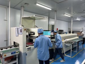
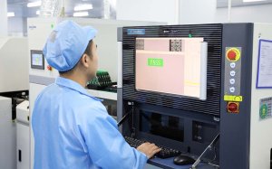
After reflow, the assembled board undergoes automated optical inspection. AOI systems capture high-resolution images of every solder joint and compare them against programmed acceptable criteria. Modern systems can inspect for solder bridges, insufficient solder, component presence, polarity, and tombstoning in seconds.
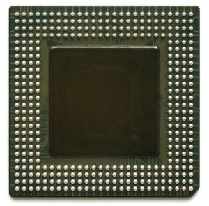
For assemblies with BGA, QFN, or other hidden-joint components, X-ray inspection provides visibility into solder joints that optical systems cannot see. X-ray reveals voiding levels in BGA balls, solder bridging under components, and insufficient solder in thermal pads. IPC standards specify acceptable voiding criteria for different component types and application classes.
The choice of a PCB assembly manufacturer with properly maintained SMT equipment and robust process controls directly determines the quality and consistency of your finished boards. When evaluating partners, look beyond equipment lists to process capability data, first-pass yield metrics, and the quality team’s approach to continuous improvement. The best SMT lines produce excellent results not because of their equipment alone, but because of the engineering expertise behind the equipment.
