Cordless power tool PCBA assemblies for motor control battery management and charging

Electric Power Tool Electronics Manufacturing

Power Tool PCB Assembly & Manufacturing

From high-current brushless motor control and intelligent triggers to battery-management systems, chargers and connected-tool modules, Keep Best PCBA builds dependable electronics for professional, industrial, garden and consumer power tools.

Prototype to VolumeScalable product launch support
High-Current AssemblySMT, THT and power devices
AOI / X-ray / FCTInspection and functional testing

One tool platform, multiple critical boards

PCBA solutions for the complete power-tool ecosystem

A modern electric tool is a compact electromechanical system exposed to stall current, switching noise, heat, vibration, conductive dust, moisture and repeated impact. Its electronics may be distributed among the tool body, removable battery, charger, dock and wireless gateway. We help power-tool OEMs and product developers translate those requirements into repeatable PCB assemblies.

Brushless DC motor-control PCBAs
Lithium battery BMS assemblies
AC/DC and multi-bay charger boards
High-current copper and bus structures
Compact trigger, LED and HMI boards
Coating, staking and ruggedization options

Electronic architecture

Where PCBAs are used in electric power tools

Customers can engage us for one controller board or an entire platform of interoperable tool, battery and charger assemblies. The following electronic functions cover the most common power-tool PCBA requirements.

01

Brushless Motor-Control PCBA

MCU, gate drivers, power MOSFETs, current shunts and phase connections commutate a BLDC motor under rapid load changes. Layout must manage high di/dt loops, heat, regenerative events and motor-cable noise in a very small enclosure.

02

Brushed-Motor Speed Controller

PWM control, power switching, soft start, braking and overload protection for cost-sensitive brushed tools. The assembly must tolerate brush noise, arcing transients, high inrush current and repeated trigger cycling.

03

Trigger & User-Control Board

Variable-speed trigger sensing, direction selection, mode buttons, torque settings and electronic brake commands. Compact geometry, dependable contact interfaces and stable low-voltage signals are important inside a vibrating handle.

04

Battery-Management System

Cell-voltage and temperature monitoring, pack protection, state-of-charge estimation, balancing, authentication and tool/charger communication. Creepage, current-path design, pack connector durability and traceability require close review.

05

Charger & Power-Supply PCBA

AC/DC conversion, power-factor functions where required, isolated feedback, charge control, cooling and pack communication for single-port, rapid and multi-bay chargers. Safety spacing and thermal performance drive the physical layout.

06

Protection & Sensor Interface

Hall sensors, temperature sensors, accelerometers, current measurement, jam detection, kickback sensing and overload protection. Low-noise signal conditioning must coexist with motor-switching edges and large current paths.

07

Lighting, Display & HMI

Work lights, status LEDs, fuel gauges, small displays, buzzers and haptic feedback. Separate compact boards and flex connections can simplify final assembly while keeping indicators visible through the product housing.

08

Wireless & Tool Tracking

Bluetooth, Wi-Fi, NFC or proprietary radio modules for settings, inventory, diagnostics, geofencing and fleet management. RF clearance, antenna placement, shielding, device identity and secure provisioning should be planned together.

09

Corded Tool Power Electronics

Triac or inverter control, soft start, constant-speed regulation, EMI filtering and mains protection for grinders, saws, sanders, routers and demolition tools. Isolation boundaries and surge performance are fundamental design inputs.

Inside a cordless power-tool platform

PCBA locations from the tool body to battery and charger

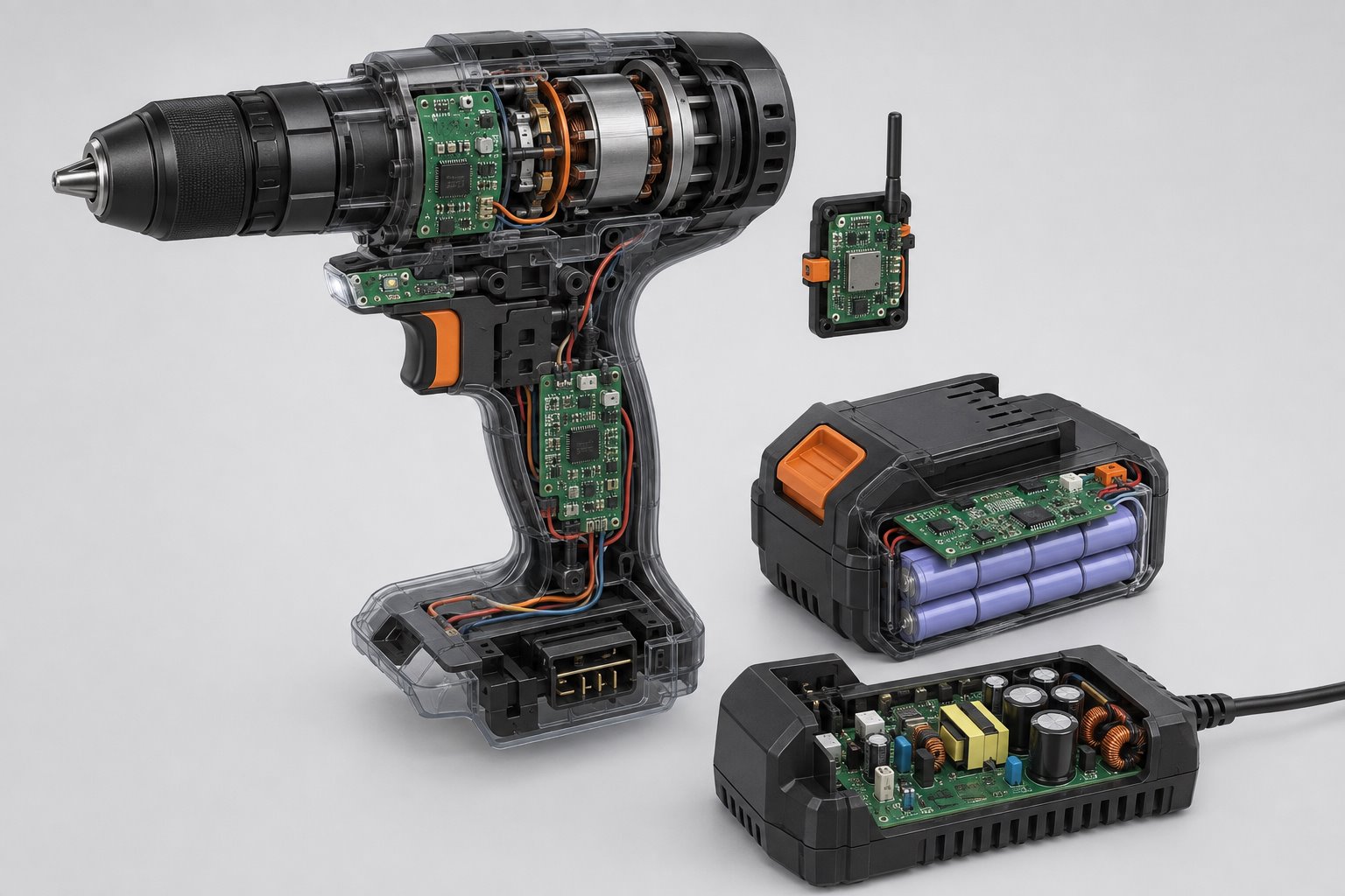
A cordless drill illustrates the distributed electronics found across many modern tools. The exact architecture varies by platform, but these board locations and functions are common in professional designs.

Cutaway cordless drill showing motor control trigger battery BMS charger and wireless PCB assemblies
Tool, battery and charger electronics form one power-and-data system; each assembly needs its own electrical, thermal and mechanical acceptance criteria.
1. Main Motor-Control PCBA

Mounted near the motor or in the handle to shorten high-current paths. It runs commutation, speed regulation, torque control, braking, stall response and protection.

2. Power MOSFET Stage

Three-phase bridge for BLDC tools or a switching stage for brushed motors. Copper area, thermal vias, heat spreaders and low-inductance connections control junction temperature.

3. Gate-Driver & Control Section

Translates MCU commands into fast, controlled switching while monitoring undervoltage, overcurrent and fault states. Clean grounding protects control logic from the power stage.

4. Current & Voltage Sensing

Shunts, amplifiers and ADC inputs measure phase or bus current for torque control, electronic clutch functions, overload response and diagnostics.

5. Rotor-Position Interface

Hall-effect sensor boards or sensorless back-EMF circuits provide commutation timing. Connectors and signal paths must resist electrical noise and vibration.

6. Trigger / Direction PCBA

Reads trigger travel, forward/reverse position and mode selections, then passes commands to the controller. Mechanical alignment and repeatable sensing are essential for user feel.

7. Work-Light & Status Board

Controls high-efficiency LEDs, battery indicators and fault/status signaling. Small rigid or flex assemblies help fit optical elements around the chuck and handle.

8. Kickback & Motion Sensor Board

An IMU or acceleration sensor can detect rapid tool rotation, drops or abnormal vibration. Placement, sampling stability and firmware thresholds affect response quality.

9. Wireless / Identification Module

Supports pairing, settings, usage records, location or fleet inventory. RF performance depends on the antenna keep-out and surrounding battery, motor and metal structures.

10. Battery-Pack BMS

Monitors series cell groups, pack current and temperature; operates protection switches; estimates charge level; and communicates with compatible tools and chargers.

11. Pack Interface & Fuel Gauge

High-current terminals, ID contacts, wake signals, LEDs and a push-button may be integrated with the BMS or placed on a small secondary board.

12. Smart Charger PCBA

Provides isolated conversion, charge regulation, pack detection, temperature qualification, cooling control and end-of-charge communication.

13. Dock / Multi-Bay Controller

Coordinates sequential or parallel charging, fan operation, status indicators, communications and power budgeting across several connected packs.

14. Accessory & Dust-Control I/O

Interfaces with extraction systems, pumps, lights or connected accessories using switched power, wireless triggers or low-voltage communication.

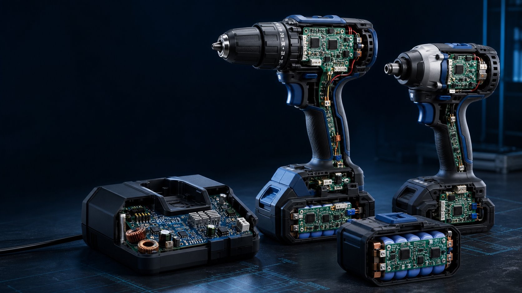
Motor controller battery and charger PCBAs used in cordless power tools
High-current motor control, intelligent battery protection and fast charging must be engineered as a compatible platform.
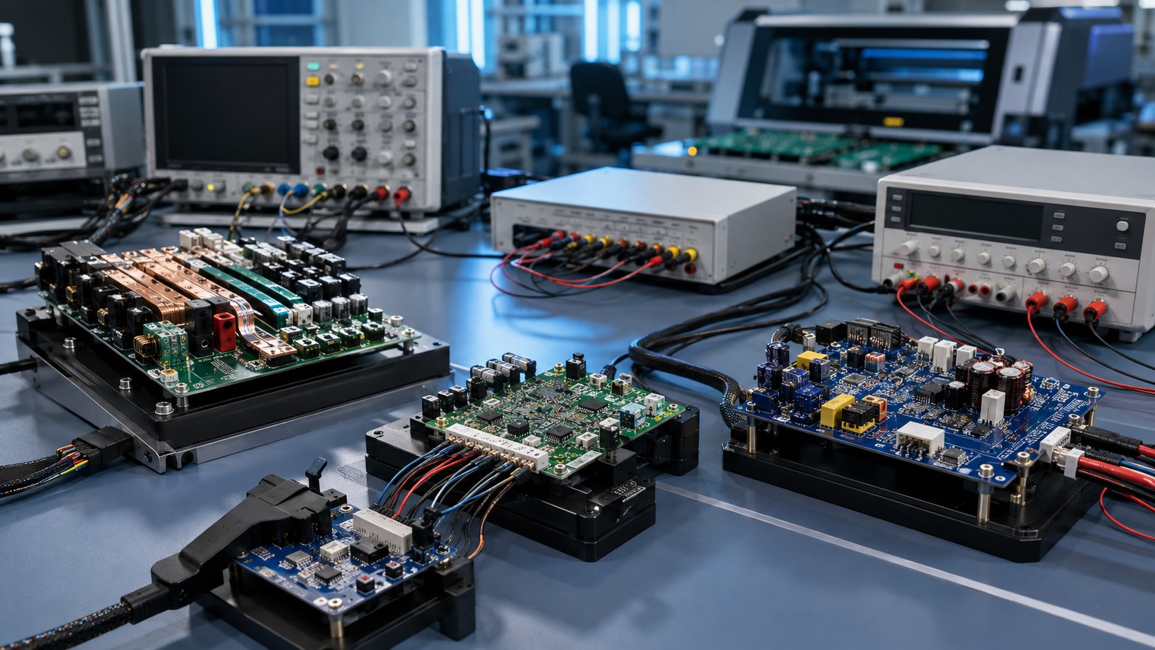
Functional testing of power-tool motor controller BMS and charger PCB assemblies
Board-level programming and functional test can cover power rails, protection thresholds, communications, sensors and controlled electronic loads.

Detailed application map

Power tool PCBA application scenarios

Different tools create very different torque, current, thermal, vibration and contamination profiles. Select the product family closest to your project to identify the likely PCBA focus.

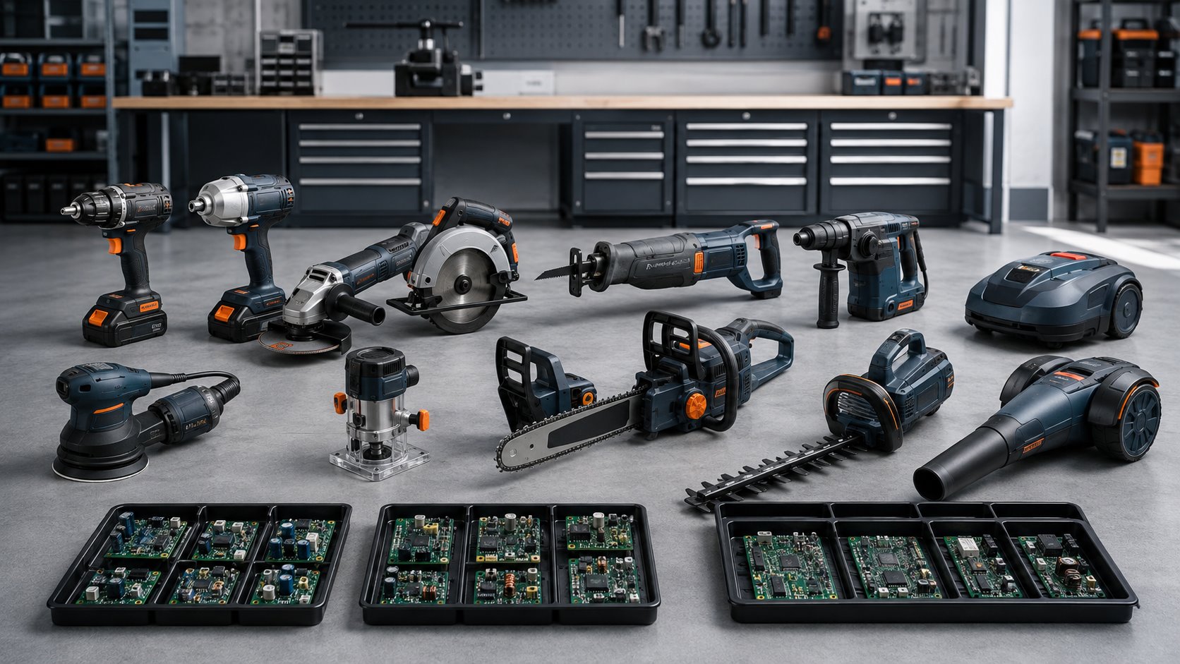
Electric power tool categories and the PCB assemblies used across each product family
Power-tool electronics span compact hand tools, high-energy cutting and concrete equipment, outdoor products, battery packs, chargers and connected fleet accessories.

Tools in the field

Recognizable products, application-specific electronics

Real operating conditions define the board-level priorities. These familiar use cases help buyers connect their product directly to the motor controller, battery, sensing and protection functions we manufacture.

Cordless Drills & Hammer Drills

Drill/drivers, percussion drills and right-angle drills combine BLDC control, variable speed, electronic clutch logic, work lighting and pack communication. The controller must respond gracefully to bit jams, rapid reversals and repeated stall events.

BLDC inverterElectronic clutchKickback sensing

Impact Drivers & Impact Wrenches

High-acceleration fastening tools impose strong mechanical shock and large current pulses. Motor controllers, triggers and battery interfaces need robust component retention, fast overcurrent response and repeatable torque-mode behavior.

Pulse currentImpact vibrationMode control

Precision Screwdrivers & Nutrunners

Assembly screwdrivers, torque-controlled nutrunners and shut-off tools use speed/torque profiles, transducer inputs, angle measurement and result communication. Low-noise acquisition and calibration support repeatable fastening data.

Torque/angleTraceable resultsLow-noise sensing

Circular, Reciprocating & Jig Saws

Electronic soft start, load-speed regulation, braking, blade-jam response and dust-system interfaces are common. High vibration and sawdust require protected components, dependable connectors and thermal margin around the power stage.

Electronic brakeJam protectionDust exposure

Angle Grinders, Polishers & Sanders

Grinders, polishers, orbital sanders and belt sanders may add constant-speed regulation, anti-restart, soft start and vibration control. Conductive dust, long duty cycles and heat near the motor make coating strategy and thermal design important.

Constant speedAnti-restartThermal control

Rotary Hammers & Demolition Tools

Rotary hammers, breakers and chipping tools expose electronics to severe repetitive impact. Rugged board mounting, staking of heavier parts, protected sensor interfaces and high-retention interconnects help preserve solder-joint reliability.

Severe shockComponent stakingHigh retention

Routers, Planers & Woodworking Tools

Routers, planers, biscuit joiners and compact woodworking tools need smooth speed regulation under changing cutter loads. Fine dust management, low-profile layouts and effective heat transfer support enclosed motor housings.

Speed regulationCompact layoutFine dust

Nailers, Riveters & Cutting Tools

Cordless nailers, staplers, riveters, shears, nibblers and cable cutters combine motor drives, solenoids, flywheels or hydraulic pumps with interlocks and cycle sensing. Peak-energy management and safe state transitions are central.

InterlocksCycle sensingPeak energy

Outdoor & Garden Equipment

Chainsaws, hedge trimmers, string trimmers, blowers, pruners and lawn equipment encounter moisture, sap, grass debris, UV exposure and wide temperatures. Sealed interfaces, corrosion protection and robust motor control extend field reliability.

Moisture resistanceWide temperatureHigh-power BLDC

Vacuums, Extractors & Pressure Equipment

Jobsite vacuums, dust extractors, pressure washers, inflators and transfer pumps use high-speed motors, pressure/flow sensors and accessory control. Electronics may coordinate automatic tool start, filters, valves and battery optimization.

Sensor controlAccessory triggerSealed I/O

Corded Professional Tools

Corded grinders, saws, drills, routers and sanders may require mains filtering, soft-start control, triac or inverter drive and isolated low-voltage logic. Creepage, clearance, surge, leakage and thermal behavior must be specified for the target market.

Mains isolationEMI filteringSurge protection

Smart Connected & Fleet-Managed Tools

Connected tools add configuration, usage counters, maintenance alerts, access control, location or inventory functions. Wireless modules, secure elements and programming records require controlled assembly and provisioning workflows.

Bluetooth/NFCSecure provisioningFleet data

Battery Packs, Rapid & Multi-Bay Chargers

Removable packs and charging systems serve an entire tool family. BMS, fuel-gauge, charger, fan-control and dock PCBAs must coordinate pack identity, temperature windows, charge current, fault handling and long-term cell protection.

BMSFast chargingPack communication

Stationary & Benchtop Equipment

Miter saws, table saws, drill presses, grinders and jobsite stations may combine higher-power drives with displays, safety interlocks, braking, dust collection and external I/O. Mixed SMT/THT construction supports terminals, relays and power magnetics.

Safety I/OMixed assemblyPower magnetics

Voltage and product platforms

PCBA priorities by power-tool architecture

Voltage labels alone do not determine the manufacturing process. Cell configuration, peak current, motor control, enclosure volume, cooling and fault-energy strategy should be reviewed together.

Platform Typical products Common electronics Primary PCBA considerations
Compact cordless Screwdrivers, inspection tools, compact drills and ratchets Small motor controller, trigger/HMI, compact BMS and USB or dedicated charger Dense layout, low standby current, limited thermal mass, small connectors and cost-efficient panelization.
Mainstream cordless Drills, impacts, saws, grinders, sanders, nailers and vacuums BLDC inverter, sensors, intelligent trigger, multi-cell BMS and fast charger High pulse current, MOSFET heat spreading, pack/tool communication, vibration and automated functional test.
High-output cordless Rotary hammers, large saws, chainsaws, blowers and concrete tools Higher-voltage inverter, parallel-cell BMS, active cooling and high-power charger Creepage/clearance, heavy copper or bus structures, fault energy, current connection resistance and thermal cycling.
Dual-pack or multi-voltage Large outdoor equipment, stationary tools and platform-sharing products Pack arbitration, balancing/monitoring, high-voltage drive and communication gateway Pack mismatch handling, connector sequencing, isolation of logic, firmware control and system-level validation.
Corded / universal motor Grinders, routers, sanders, saws, drills and demolition tools Triac control, soft start, speed regulation, mains filter and safety switching Mains spacing, surge/ESD, leakage, heat near power devices, EMI compliance and reinforced mechanical retention.
Corded BLDC / inverter Premium grinders, saws, dust extraction and specialized industrial tools Rectification/PFC where needed, isolated supply, inverter, sensing and HMI High-voltage assembly, insulation system, power magnetics, thermal interfaces and load-regulation test coverage.

Engineering priorities

Design and manufacturing requirements for power-tool PCBAs

The correct build specification depends on the board location, tool duty cycle, motor and battery system, environment and consequence of a fault. Our engineering review focuses on the following risk areas before production.

Requirement Why it matters in power tools Typical PCBA response
High-current integrity Acceleration, stall, impact and cutting loads can create short, high-amplitude current pulses. Copper-weight review, wide current paths, busbars or copper inserts where justified, via arrays, low-resistance joints and current-path temperature validation.
Thermal management MOSFETs, shunts, magnetics and chargers operate in compact enclosures with dust filters or limited airflow. Thermal vias, balanced copper, IMS or heat-spreader options, controlled interface materials, component derating and temperature-rise testing under representative loads.
EMI/EMC control Fast power switching, motor leads and brush arcing can disturb sensors, radios, pack communication and nearby equipment. Minimized switching loops, return-path review, filtering, shielding provisions, gate-resistor control, separation of power and logic, and pre-compliance support.
Transient & fault protection Hot-plugging, regenerative braking, motor inductance, reversed packs and charger faults stress electronics. TVS and snubber networks, coordinated overcurrent protection, reverse-polarity strategy, safe MOSFET operation and controlled fault-injection test plans.
Shock & vibration Impacts, hammer mechanisms, imbalance and drops load components, solder joints and connectors repeatedly. Component orientation review, suitable land patterns, staking of heavy parts, connector retention, board supports and vibration-aware acceptance testing.
Dust, moisture & chemicals Sawdust, concrete dust, metal particles, oil, resin, grass moisture and cleaning products can contaminate assemblies. Cleaning, conformal coating, selective masking, drainage/keep-out planning, corrosion-resistant finishes and process verification for coating coverage.
Compact mechanics Controllers must fit around motors, gearcases, cooling paths, triggers and ergonomic handles. Fine-pitch SMT, double-sided assembly, rigid-flex or small daughterboards, 3D clearance review and controlled placement of tall or heat-sensitive parts.
Battery safety & traceability Cell protection and pack identity depend on correct sensing, firmware and power-component assembly. Lot and serial options, programming verification, sense-path inspection, protection-threshold FCT, controlled soldering near cells and clear revision records.
Connector durability Battery packs, accessories and chargers experience thousands of insertion cycles, vibration and contamination. Through-hole or reinforced terminals, selective solder control, coplanarity checks, retention features and contact-resistance tests under specified loads.
Lifecycle & cost control Tool families often remain in the market for years while semiconductors and cells change. Approved-vendor control, alternate-part review, BOM risk monitoring, panel utilization, design-for-test and documented engineering-change management.

From design data to tested assemblies

Our power tool PCBA manufacturing workflow

A controlled handoff from prototype to volume production reduces electrical, thermal and supply-chain surprises. Keep Best PCBA can coordinate PCB fabrication, component sourcing, assembly, programming, inspection, functional test and protective processes.

1. RequirementsTool function, motor, battery, peak current, environment, volumes and test strategy.
2. DFM / DFAStack-up, copper, stencil, spacing, polarity, terminals, thermal interfaces and test-point review.
3. Supply ChainBOM validation, authorized sourcing, power-device matching, alternates and lifecycle risks.
4. AssemblySMT, selective or wave solder, press-fit, mixed technology, thermal materials and controlled reflow.
5. InspectionSPI, AOI, X-ray, polarity checks, terminal inspection and workmanship acceptance.
6. Program & TestFirmware, current-limited bring-up, ICT/FCT, protection checks, coating and final packing.

Power tool PCBA functional test for motor controllers battery management and chargers
Test coverage can be divided by board function so tool controllers, battery BMS, charger power stages and compact interface boards each receive appropriate stimuli and limits.

High-Current & Heavy-Copper Assembly

Process planning for thicker copper, large thermal pads, bus structures, shunts, power MOSFETs, terminals and mixed-mass solder joints.

Power-Device Thermal Control

Stencil design, voiding review, controlled reflow, thermal-interface installation and inspection around exposed-pad power packages.

Programming & Secure Provisioning

Customer-defined firmware loading, serial handling, configuration records and controlled device-identity or wireless provisioning steps.

Motor-Controller Functional Test

Checks may cover power rails, gate-drive behavior, phase outputs, sensor inputs, communications, braking signals and simulated load conditions.

BMS & Charger Test

Cell-voltage simulation, thermistor inputs, protection thresholds, pack communication, isolated power, fan control and charge-state outputs.

Ruggedization Options

Cleaning, conformal coating, selective masking, staking, adhesive control and other protective processes based on the product environment.

Standards note: power tools and their battery/charger systems may reference IPC-A-610 and J-STD-001 workmanship criteria together with product-level safety and EMC requirements such as IEC/UL 62841, IEC/UL 60335-2-29, IEC 62133-2, UL 2595, UN 38.3, CISPR 14-1 or regional equivalents. The applicable edition, market, construction category and validation plan must be defined by the customer and product-certification team; PCBA workmanship alone does not establish end-product compliance.

Frequently asked questions

Power tool PCBA FAQs

Can you build both tool motor controllers and battery BMS PCBAs?

Yes. A project can include the in-tool motor-control board, trigger or HMI boards, removable-pack BMS, charger power electronics and wireless modules. Share the electrical, thermal, firmware and test requirements for each assembly so the family can be reviewed as one system.

Do you support high-current brushless motor-control boards?

Yes. We can review PCB copper, MOSFET packages, current sensing, thermal interfaces, connectors and mixed-technology assembly. Peak/stall current, PWM frequency, duty cycle, cooling path and acceptance temperature should be provided for process planning.

Can you assemble heavy-copper or metal-core PCBs?

Heavy-copper, thermal-spreader and metal-core options can be evaluated when the design requires additional current or heat-handling capability. Final selection depends on layer structure, component technology, flatness, soldering profile, isolation needs and mechanical integration.

What files are needed for a power tool PCBA quotation?

Gerber or ODB++ data, drill files, BOM, centroid data, assembly drawings and quantities are the usual starting point. Add voltage/current data, motor type, firmware, test instructions, coating, traceability, target IPC class and any product-safety spacing requirements.

How do you inspect exposed-pad MOSFET, QFN and BGA joints?

X-ray inspection can be used for hidden joints and thermal pads that are not visible to AOI. It is normally combined with solder-paste inspection, reflow-profile control, AOI and electrical or functional testing according to package and risk.

Can you apply conformal coating for dusty or outdoor tools?

Yes. Coating material, target thickness, masking and keep-out areas, cure process and inspection criteria should match the expected dust, moisture, chemical and temperature environment. Coating is one part of product-level environmental protection.

Do you provide programming and functional testing?

Yes. We can load customer-provided firmware and work with an existing fixture or help plan board-level FCT. Coverage may include rails, current consumption, gate outputs, sensors, communications, LEDs, protection states and simulated tool, pack or charger interfaces.

Can you test BMS protection without connecting production cells?

A customer-approved cell simulator and electronic load can be used to exercise sense inputs and selected protection functions at board level. The fixture, safe limits, sequence and pass/fail thresholds must be agreed before production.

Do you support prototypes and design revisions before volume production?

Yes. Prototype and low-volume builds are useful for validating motor behavior, thermals, firmware, mechanics and battery communication together. DFM feedback and defect analysis can then be incorporated into controlled revisions before ramp-up.

How do you manage component and firmware traceability?

Options can include controlled BOM revisions, approved vendor and date/lot records, programmed firmware version, serialized labels, test result association and engineering-change records. Required traceability depth should be stated in the quotation package.

From use case to tested assembly

Build electronics for the way your tool is actually used

Share the motor, battery platform, peak current and operating environment. We will focus the review on the risks that matter for your application.

Motor controlBattery BMSFast chargersRuggedization

Start your project review

Send us your power tool PCBA project

Upload your design package and tell us the quantity, test requirements and environmental conditions.

Get A Quote

Fill in your requirement information and upload Gerber and BOM files, we will give you a quote within 24 hours.

Get A quote

Fill in your requirement information and upload Gerber and BOM files, we will give you a quote within 24 hours.