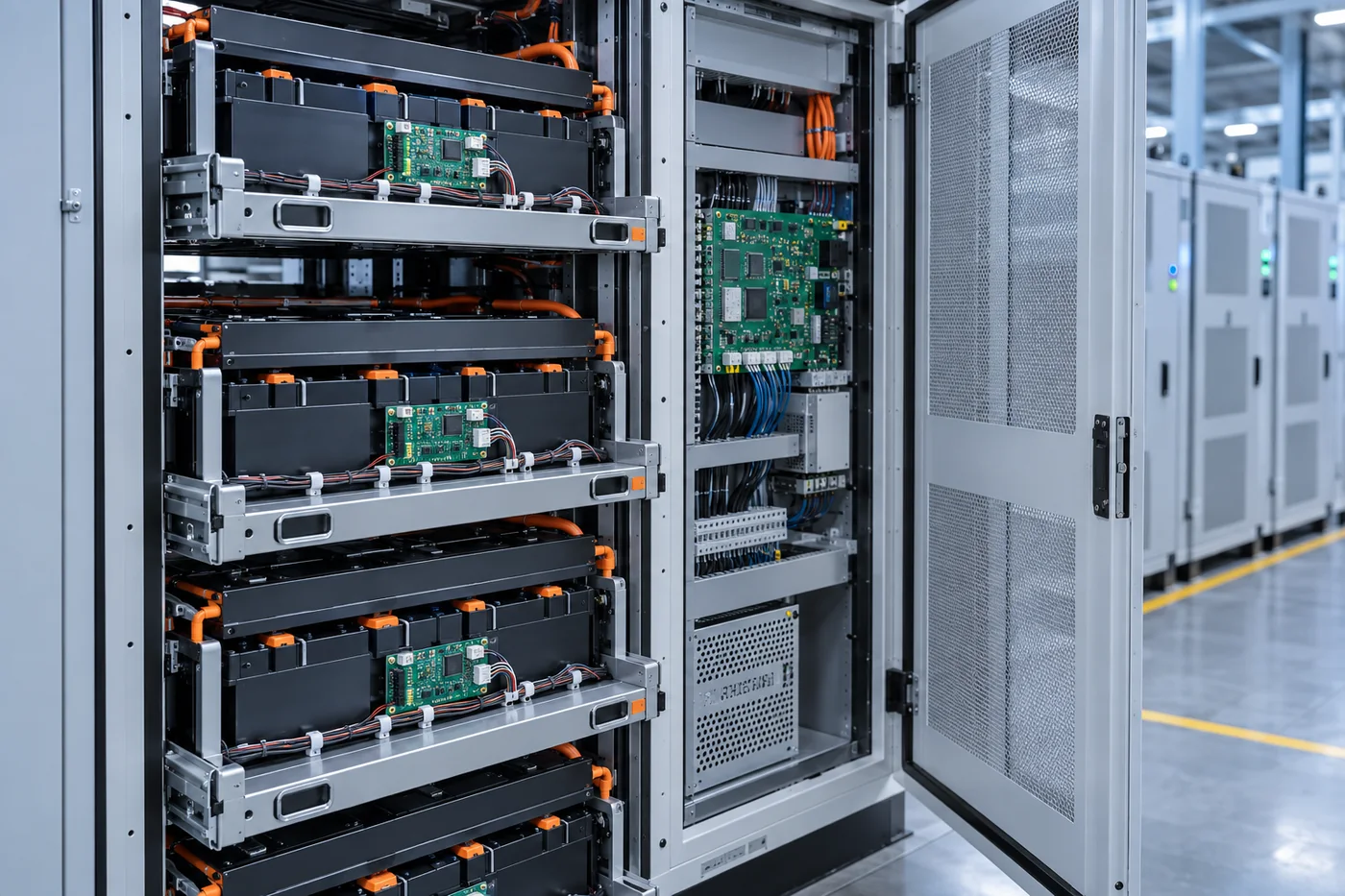
Energy storage battery cabinet with an installed BMS PCB assembly

Cell insight · Rack coordination · Dependable control

Energy Storage
BMS PCBA

PCB assembly for cell monitoring, battery-rack control, balancing, isolated communications and auxiliary power in residential, commercial and utility energy-storage systems.

01Distributed architectureCMU, BCU and interface assemblies
02Mixed-signal precisionLow-noise sensing beside power circuits
03Build-to-spec supportPrototype, sourcing, assembly and test

A distributed electronic system

One battery system.
Several PCBA layers.

Commercial energy storage battery rack showing layered BMS control hardware
Module monitoring → rack control → site energy management

An energy-storage BMS may spread measurement, control and communications across every module and rack. Each board has a different signal environment, connector count, thermal load and isolation requirement.

Keep Best PCBA manufactures to customer-supplied design data and agreed test specifications. Share the battery chemistry, series-cell count, voltage class, system topology, environmental conditions and compliance requirements so the assembly scope can be reviewed accurately.

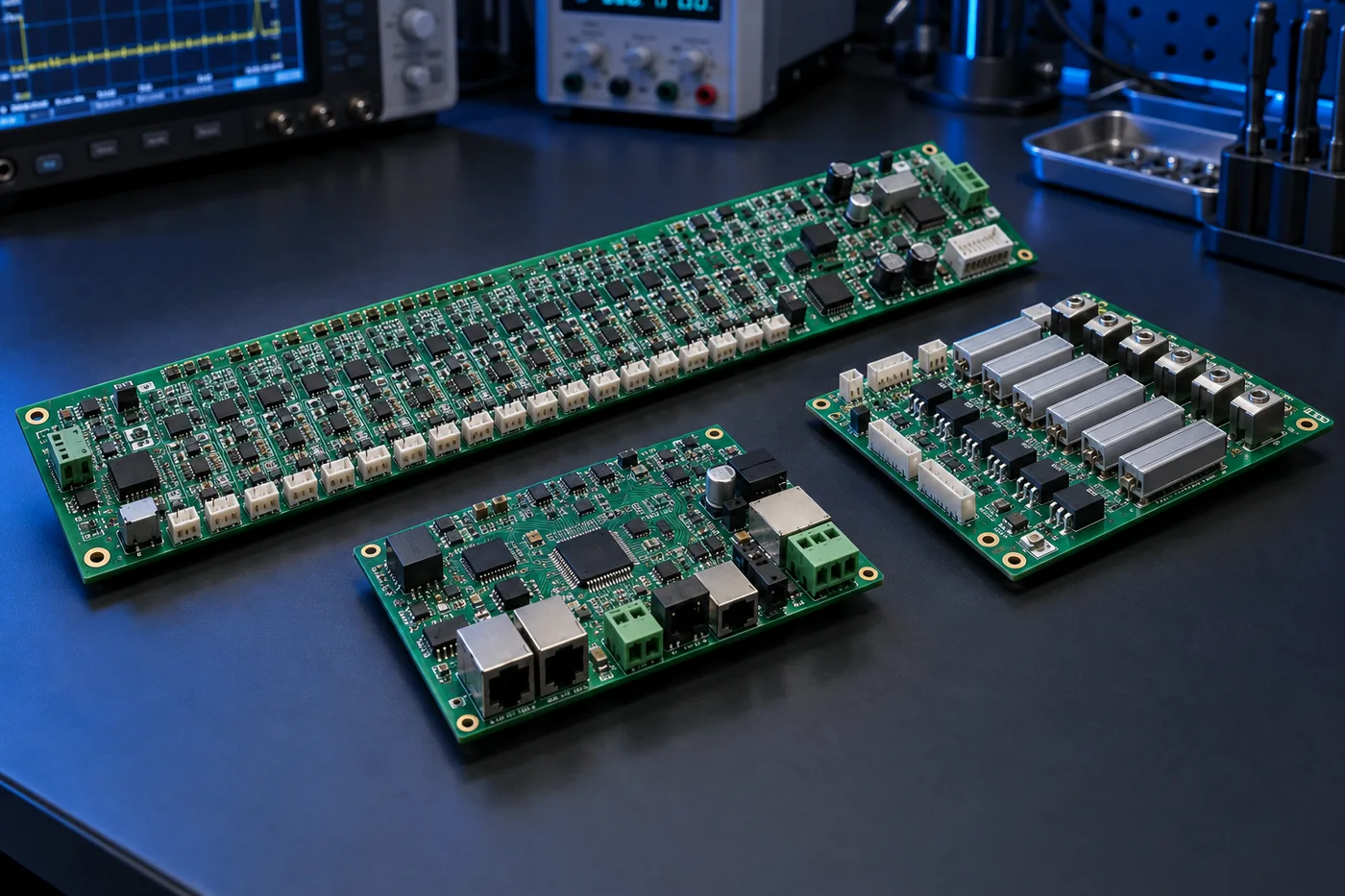
Boards in the control stack

From individual cells to the energy-management system

A clear board map helps define measurement channels, connectors, isolation boundaries, communications and functional-test coverage before quotation.

01 / MODULE

Cell Monitoring Unit (CMU)

Measures series-cell voltages and multiple temperatures close to the battery module. Long connector rows, precision front ends and daisy-chain links require careful assembly and inspection.

  • Cell-voltage inputs
  • NTC temperature channels
  • Isolated daisy-chain interface
02 / RACK

Battery Control Unit (BCU)

Coordinates module data, state estimation, rack contactor commands, fault handling, data logging and communication with the PCS or site controller.

  • MCU and memory
  • CAN / RS485 / Ethernet
  • Contactor and pre-charge I/O
03 / BALANCE

Balancing PCBA

Passive resistor networks or active energy-transfer circuits reduce cell mismatch according to the customer’s control strategy. Thermal design and connector mapping are central build inputs.

  • Passive or active topology
  • Thermal paths and spacing
  • Channel-by-channel verification
04 / INTERFACE

High-Voltage & Sensor Interface

Interfaces pack current, bus voltage, insulation-monitoring signals, service disconnects and auxiliary sensors while maintaining the specified isolation boundary.

  • Current-sensor interface
  • HV measurement input
  • Isolation and protected I/O
05 / AUXILIARY

Power & Communication Board

Provides isolated DC/DC rails, wake and sleep functions, gateway communication, fan or heater outputs and service ports for commissioning and diagnostics.

  • Isolated auxiliary power
  • Gateway and service ports
  • Fan, heater and alarm outputs

Signal and control path

A practical view of the BMS electronics chain

The exact architecture varies by battery chemistry, system voltage and supplier ecosystem. This simplified map shows the PCBA interfaces that are commonly reviewed during manufacturing preparation.

Analog front end: cell voltage and temperature acquisition with channel filtering and connector mapping.

Rack control: estimation, fault state logic, contactor sequencing and event records in the BCU.

External link: isolated communication to the power-conversion system, site EMS, service tools and remote gateway.

Six real-world environments

Choose the storage product closest to your project

Select a scene to compare the board-level priorities. Every design still needs its own electrical, environmental and test review.

01 / SELECTED APPLICATION

Home & Small Commercial Storage

Compact storage products combine cell monitoring, wake control and inverter communication in a small serviceable enclosure.

Typical board focus

Compact CMU / BCULow standby currentCAN / RS485Installer-friendly connectors

Discuss this application

Before quotation

Define the electrical, environmental and acceptance boundaries

BMS projects move faster when the manufacturing package identifies both the board data and the system conditions that affect assembly and test.

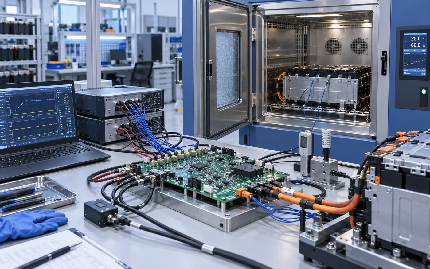
Energy storage BMS PCBA connected to an environmental test chamber and electrical validation equipment
Environmental and electrical limits should be translated into a repeatable board-level validation plan.
VALIDATION CONTEXT

Share the conditions behind the numbers

Temperature, humidity, cell-simulation range, sleep current and communications limits affect fixture design, component handling and pass/fail criteria.

  • Operating and storage temperature
  • Channel accuracy and calibration method
  • Normal, wake, sleep and fault states
01

Battery architecture

Chemistry, series-cell count, module and rack topology, operating voltage and auxiliary supply range.

02

Measurement channels

Cell voltage, pack voltage, current, temperature and any insulation or leakage monitoring interfaces.

03

Balancing approach

Passive or active method, maximum balance current, duty cycle and thermal boundary conditions.

04

Communications

CAN, RS485, Ethernet, isolated daisy chain, service interface, termination and programming requirements.

05

Environment

Temperature, humidity, condensation, pollution level, altitude, vibration and coating or potting requirements.

06

Acceptance package

Workmanship class, inspection plan, test limits, traceability, change control and required customer approvals.

Assembly and verification

A production flow built around the approved data package

Inspection and test are selected according to component mix, board construction, risk points and the customer’s acceptance specification.

Energy storage BMS printed circuit boards in automated inspection and production test fixtures
FROM ASSEMBLY TO RELEASEInspection and test coverage follows the approved board data and product risk points.
01

Engineering review

Gerber/ODB++, stack-up, BOM, drawings, panel, test and traceability requirements.

02

Material control

Approved manufacturers, alternates, date codes, moisture handling and incoming checks.

03

SMT & THT assembly

Fine-pitch ICs, long connectors, relays, transformers and selective or hand-soldered parts.

04

Inspection

SPI, AOI, X-ray where appropriate, polarity, solder fill, cleanliness and visual workmanship.

05

Programming & test

Customer firmware plus agreed ICT, boundary, communications or functional test coverage.

06

Protection & release

Coating, curing, serialization, final inspection, records and specified packaging.

Test area Typical checks Customer input required
Power rails Input current, regulated rails, isolated supplies, sleep and wake states Nominal ranges and pass/fail limits
Measurement channels Simulated cell voltage, temperature inputs, scaling and channel mapping Calibration method, accuracy and limits
Communications CAN, RS485, Ethernet or daisy-chain response and termination Protocol, baud rate and test commands
Control outputs Contactor, pre-charge, fan, heater, relay and alarm outputs under safe loads Fixture interface and output thresholds
Programming Bootloader, firmware, configuration, device identity and checksum verification Approved files and revision rules

Project questions

Useful answers before you send a BMS design

Energy-storage projects differ widely. These answers describe the information needed to review an assembly request responsibly.

Do you design the BMS algorithm or safety concept?

This page describes PCBA manufacturing and agreed board-level test support. Battery algorithms, system protection strategy, functional safety, hazard analysis and final validation remain with the customer or designated design authority unless a separate written engineering scope is agreed.

Can you assemble both CMU and BCU boards?

Yes, projects may include module monitoring, rack control, balancing, communication, auxiliary-power and interface boards. Send the complete board list and show how revisions, firmware and test fixtures relate to each assembly.

Can cell-simulation testing be included?

Provide the channel count, simulated input ranges, accuracy limits, connector pinout, test sequence and expected communications response. Fixture development and production coverage are reviewed before quotation.

What certifications can you support?

Tell us the standards, customer approvals, workmanship class and documentation required for the specific product. Certification applicability belongs to the final system and supply-chain scope; no certification is implied by this webpage.

Can conformal coating or potting be applied?

Coating, selective masking, cure control and potting can be reviewed when material, thickness, keep-out areas, test points and acceptance criteria are identified on the drawing.

What files should be included with the RFQ?

Send Gerber or ODB++, BOM with approved manufacturers, centroid data, fabrication and assembly drawings, schematics where available, firmware, test requirements, expected quantities and delivery plan.


Project review

Send your BMS PCBA requirements.

Share the board type, quantity, target date and test scope. Attach Gerber/ODB++, BOM and drawings when available.

Get A Quote

Fill in your requirement information and upload Gerber and BOM files, we will give you a quote within 24 hours.

Get A quote

Fill in your requirement information and upload Gerber and BOM files, we will give you a quote within 24 hours.