
SMT vs Through-Hole Assembly: Technology Comparison and Best Use Cases
For decades, the question of SMT vs through-hole assembly has shaped how engineers design circuit boards. Surface mount technology dominates modern electronics manufacturing, but through-hole technology has not disappeared. In fact, it remains essential for specific applications where SMT cannot meet mechanical, thermal, or electrical requirements.
Understanding the strengths and limitations of each technology helps designers make informed decisions that balance manufacturability, cost, and reliability. This article provides a detailed comparison to guide those decisions.
Surface Mount Technology: The Modern Standard
Surface mount technology places components directly onto pads on the PCB surface, held in place by solder paste before reflow. The components are smaller, lighter, and available in finer pitches than through-hole equivalents. This miniaturization is the fundamental advantage that drove SMT to dominate electronics manufacturing.
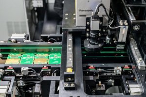
The benefits of SMT extend beyond size. Automated pick-and-place equipment places SMT components at rates exceeding tens of thousands per hour, dramatically faster than manual or automated through-hole insertion. Both sides of a PCB can be populated with SMT components, effectively doubling available board area. And the lower profile of SMT components improves high-frequency performance by reducing parasitic inductance and capacitance from lead lengths.
SMT also enables higher circuit density. Trace widths and spacing can be finer because SMT pads are smaller than through-hole pads, which must accommodate drill holes. This density advantage is why smartphones, laptops, and virtually all consumer electronics use predominantly SMT designs.
However, SMT has limitations. The smaller solder joints have less mechanical strength than through-hole connections, making them less suitable for components subject to significant mechanical stress. SMT components also have lower thermal mass, which can be a disadvantage for power devices that need to dissipate heat through their leads. And the reflow process required for SMT assembly exposes all components to a thermal profile that some sensitive parts cannot tolerate.
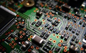
Through-Hole Technology: Where It Still Matters
Through-hole technology mounts components by inserting their leads through drilled holes in the PCB and soldering them on the opposite side. The resulting mechanical bond, with the lead passing through the board and anchored by solder on both sides, provides significantly greater mechanical strength than a surface mount solder joint.
This mechanical robustness makes through-hole the preferred choice for components that experience physical stress. Connectors that are repeatedly mated and unmated, large electrolytic capacitors that vibrate under mechanical load, transformers and inductors with significant mass, and power semiconductors in TO-220 or TO-247 packages all benefit from through-hole mounting.
Through-hole assembly also excels in prototyping and low-volume production. Hand soldering through-hole components requires less specialized equipment than SMT assembly, making it accessible for small-scale builds. The larger component sizes and visible leads make inspection easier and rework more straightforward than for fine-pitch SMT devices.
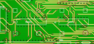
The drawbacks are equally clear. Through-hole components are larger, consume more board area, and cannot be placed on both sides of the board. Assembly is slower, whether by hand or by automated insertion equipment. Wave soldering, the standard automated process for through-hole assembly, requires careful process control to avoid defects like solder bridges and insufficient hole fill. And the drilled holes consume board real estate, limiting routing density.
Mixed-Technology Assembly: Combining Strengths
Many practical designs use both technologies on the same board. A typical mixed-technology assembly uses SMT for the majority of components, including all fine-pitch ICs and small passives, while reserving through-hole mounting for specific components that require it: connectors, high-power devices, large capacitors, and transformers.
Mixed-technology assembly requires careful process planning. The SMT components are typically placed and reflowed first. Then through-hole components are inserted and soldered using wave soldering or selective soldering. This sequence prevents the wave soldering process from disturbing previously reflowed SMT joints, though the thermal exposure of wave soldering on SMT components must be considered in the design.
For high-reliability applications, some designs use pin-in-paste technology, where through-hole leads are soldered using solder paste during the SMT reflow process. This eliminates the need for a separate wave soldering step and reduces thermal exposure. However, pin-in-paste requires specific design conditions: the hole-to-lead ratio must allow sufficient paste volume to fill the hole, and the stencil aperture must be designed to deposit the correct paste volume.
Cost and Manufacturability Comparison
The cost difference between SMT and through-hole assembly depends heavily on volume. At high volumes, SMT is significantly cheaper per component due to the speed of automated placement. A pick-and-place machine places an SMT component in a fraction of a second, while automated through-hole insertion is slower and manual through-hole soldering is slower still.
At very low volumes, the cost advantage shifts. The NRE charges for SMT assembly, including stencil fabrication and placement programming, may exceed the per-board savings for small quantities. Through-hole assembly, especially if done manually, has minimal setup costs. For prototype runs of fewer than ten boards, through-hole may be more economical.
Board fabrication cost also differs. Through-hole boards require drilled holes for every component lead, which increases fabrication cost and time. High-density SMT boards may require more layers to route the dense interconnections, which also increases fabrication cost. The cost tradeoff depends on the specific design complexity and board technology.

Reliability Considerations Under Stress
Thermal cycling reliability differs between the two technologies. SMT solder joints experience shear stress during thermal cycling due to the mismatch in coefficient of thermal expansion between the component, solder, and board. Over many cycles, this stress can cause fatigue cracking, particularly on larger components with greater CTE mismatch. Through-hole solder joints distribute stress over a larger solder volume and the lead itself provides mechanical compliance, making them more resistant to thermal cycling fatigue.
Mechanical shock and vibration testing typically shows through-hole joints outperforming SMT joints for the same component type. The lead passing through the board acts as a stress absorber, while SMT joints transmit stress directly to the copper pad and the component termination. For applications subject to significant mechanical stress, through-hole mounting of critical components remains the safer choice.
However, for components not subject to mechanical stress, SMT reliability is excellent. The smaller component mass reduces the forces experienced during vibration, and the lower profile reduces the leverage arm for shock forces. In many applications, SMT reliability meets or exceeds through-hole reliability because the components themselves are less susceptible to mechanical damage.
Decision Framework for Your Design
Use SMT exclusively when your design fits within the technology limits: component power dissipation is within SMT package capabilities, no components require mechanical stress resistance, board density is important, and production volume justifies the NRE costs. This covers the majority of modern consumer and industrial electronics.
Use through-hole when mechanical robustness is critical, components are too large or heavy for SMT, production volumes are too low to justify SMT NRE costs, or the design includes power devices requiring through-hole thermal management. Many industrial, aerospace, and military applications retain through-hole components for these reasons.
Use mixed technology when the design requires SMT for density but needs specific through-hole components for mechanical or power requirements. This is the most common approach for industrial electronics, automotive systems, and power electronics. Work with your PCB assembly manufacturer early in the design process to optimize the technology mix for both performance and manufacturability.
The choice between SMT and through-hole is not binary. The best designs leverage both technologies where each performs best, creating assemblies that are dense, reliable, and cost-effective. A full-service PCBA partner with experience in both technologies can guide these decisions and ensure the chosen technology mix is manufacturable at the target cost and quality level.