



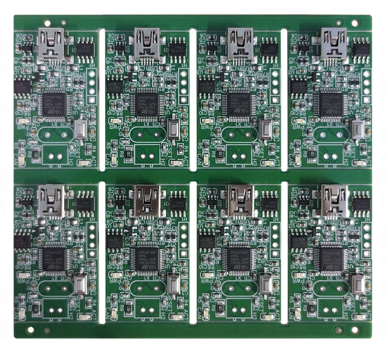
Reflow soldering is a core process in SMT assembly; improper control of thermal shock can easily lead to component damage and soldering defects. This article systematically outlines the causes, mechanisms and solutions for ten common faults, including component displacement, tombstoning, cold solder joints and bridging. It covers key aspects such as temperature curve optimisation, solder paste management and screen printing parameter control, to assist in rapid troubleshooting and improve soldering yield.

1.Fundamentals of the Reflow Soldering Process
Reflow soldering achieves electrical connection between surface-mount components and the PCB through uniform heating. Currently, the industry primarily employs far-infrared heating or hot-air convection processes. Process stability directly determines the yield of the assembly process, with the core control factor being thermal shock during soldering—excessive thermal stress can lead to component cracking, delamination or functional failure. Vapour-phase soldering, which utilises fluorinated inert solvents as a heat transfer medium, carries the risk of solvent ingress into components without sealed structures, potentially compromising the performance of electromechanical components, thus limiting its scope of application.
Reflow soldering defects are categorised into two main types. Metallurgical defects include interface bonding issues such as cold solder joints, lack of wetting, and poor wetting. Geometric defects include solder joint abnormalities such as tombstoning, bridging, capillary action, solder balls, and voids.

2.Component Displacement Failures
Causes:
Deviations in placement coordinates result in components not being aligned with the centre of the pad. Insufficient solder paste or low placement pressure leads to components not being securely fixed. Excessive flux content in the solder paste causes drag forces during the reflow stage due to flux flow.
Solutions:
Calibrate the placement machine’s vision positioning system to ensure coordinate accuracy. Increase the amount of solder paste dispensed and adjust the placement pressure to the midpoint of the process window. Select solder paste with low flux content to reduce fluid drag forces during reflow.

3. Unmelted Solder Paste Residue
Causes:
Reflow temperature set below the melting point of the solder paste. Solder paste has deteriorated due to improper storage, losing its activity. Excessive preheating causes premature decomposition of the flux, rendering it ineffective as a heat transfer medium.
Solutions:
Inspect and repair the heating modules; set the peak temperature according to the solder paste specification sheet. Strictly adhere to cold storage guidelines; inspect the solder paste condition prior to use and remove any hardened surface layers. Optimise pre-heating parameters by shortening the duration or reducing the temperature to a reasonable range.
4.Insufficient Solder Volume at Joints
Causes:
Insufficient solder paste deposition, preventing the formation of full joints. Poor wettability of pads or leads, hindering solder wetting and spreading. Reflow time is too short, preventing the solder from melting and flowing sufficiently.
Solutions:
Increase the area or thickness of the stencil apertures to enhance the volume of solder paste. Switch to a more active solder paste, or treat the pins with a dip process to remove oxidation layers. Extend the time spent above the liquidus line to ensure the solder wets and spreads fully.

5.Excessive Solder on Joints
Causes:
Excessive stencil aperture size resulting in excessive solder paste. Solder paste viscosity is too low, causing solder overflow during printing.
Solutions:
Reduce the stencil aperture size to match the actual requirements of the pads. Select a solder paste with higher viscosity to enhance resistance to sagging after printing.
6.Component Tombstoning
Causes:
SMT placement misalignment leading to uneven force distribution at both ends. High flux content causing uneven buoyancy. Solder paste thickness is too thin, resulting in insufficient holding force. Rapid heating or uneven temperature distribution causes asynchronous melting at both ends. Asymmetrical pad design leads to significant differences in thermal capacity. The surface tension characteristics of tin-lead solder paste are prone to causing tombstoning. Differences in pin wettability lead to unbalanced wetting forces.
Solutions:
Adjust the screen printer parameters to ensure the solder paste is centred, and calibrate the placement coordinates. Select low-flux or halogen-free solder paste. Increase stencil thickness to enhance solder paste volume. Optimise the temperature profile to reduce the slope and improve oven temperature uniformity. Design symmetrical pads in accordance with IPC standards to standardise thermal capacity. Switch to lead-free solder paste containing silver or bismuth to improve wetting characteristics. Screen components with consistent solderability, or perform uniform immersion pre-treatment.
7.Solder Ball Defects
Causes:
Excessively rapid heating causes rapid flux evaporation, carrying solder powder and causing splatter. Solder paste absorbs moisture; evaporation of this moisture causes splatter. Solder paste oxidises and deteriorates, reducing its reactivity. Contaminated pads hinder wetting, causing solder to contract into balls. Excessive placement pressure forces out solder powder. Excess solder paste causes surplus material to aggregate into balls during reflow.
Solutions:
Reduce the preheat ramp rate to extend the solvent evaporation phase. Maintain storage humidity below 60% RH and ensure sufficient preheating before use. Replace the solder paste with a fresh batch and shorten the preheat time to minimise oxidation. Clean oil residues from the pad surface or use a high-activity solder paste. Reduce placement pressure to the value recommended in the component specifications. Reduce the stencil aperture size and lower the squeegee pressure to control the amount of paste applied.
8.Cold Solder Joints
Causes:
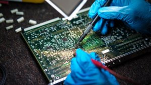
Oxidation or contamination of pads or leads, resulting in insufficient solderability. Inappropriate printing parameters leading to uneven solder paste coverage. Unreasonable temperature profile settings, resulting in insufficient wetting.
Solutions:
Strengthen incoming inspection and reject batches showing oxidation or discolouration. Reduce solder paste viscosity and adjust squeegee pressure and speed to achieve uniform transfer. Increase peak temperature or extend the liquid phase time to ensure adequate metallurgical bonding.
9.Bridging Defects
Causes:
Solder paste viscosity is too low, causing it to collapse and connect adjacent pads during reflow. Excessive printing leads to solder overflow. Repeated printing at the same location causes accumulation. Rapid heating causes the solder paste to liquefy and spread too quickly.
Solutions:
Increase the metal content or viscosity grade of the solder paste; change the grade if necessary. Reduce the stencil aperture size and lower the squeegee pressure. Eliminate repeated printing and adopt a single, precise application. Reduce the reflow ramp rate and extend the melting transition time.
10.Solder Paste Collapse
Causes:
Poor thixotropy of the solder paste, resulting in an inability to retain its shape after printing. Excessively high ambient temperature causing softening and deformation.
Solutions:
Select a solder paste with a thixotropy index that meets process requirements. Maintain workshop temperature within the range of 22 to 26 degrees Celsius and avoid the influence of local heat sources.
11.Poor Washability and White Residue
Causes:
Poor design of the flux washability, resulting in residue after cleaning. Incompatible cleaning agent type, unable to penetrate fine pores. Inappropriate cleaning parameters, with insufficient time or dosage.
Solutions:
Select water-based or semi-water-based washable solder paste to address the issue at source. Use a dedicated cleaning agent to ensure good solubility of flux residues. Extend the cleaning time, increase the circulation flow rate of the cleaning agent, and use ultrasonic assistance where necessary.
12.Recommendations for Systematic Control
Although reflow soldering faults manifest in various forms, the core causes are concentrated in four dimensions. Temperature control must ensure that the temperature profile complies with the solder paste specifications and that the uniformity of temperature within the oven chamber meets standards. Solder paste management covers storage conditions, shelf life, and re-warming protocols. Positioning accuracy involves stencil fabrication, printing parameters, and component placement coordinates. Cleanliness encompasses pad preparation, environmental control and cleaning processes.
Standardised operating procedures should be established for daily production, with enhanced management of the solder paste’s entire lifecycle. Regular maintenance of the reflow oven’s thermal performance should be carried out, alongside first-piece verification and process monitoring, to prevent faults at source and ensure the stable and reliable quality of SMT assembly.
