
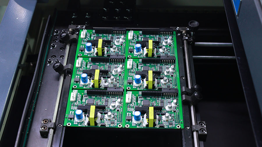
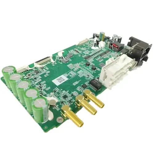
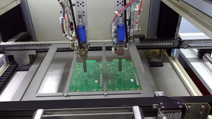
Modern electronics live or die by their solder joints. A single cold joint, a hidden BGA void, or a misaligned 0201 component can turn a six-month product roadmap into a recall campaign. That is why PCB assembly quality control has become the single most important differentiator between a contract manufacturer that scales and one that bleeds money through rework, scrap, and warranty claims. The good news is that today’s playbook for PCB assembly quality control is well documented, repeatable, and backed by global standards that any serious PCB assembly manufacturer can implement.
This guide walks through the complete PCB assembly quality control framework used by professional electronics manufacturing services in 2026. You will learn which IPC standards govern acceptance, how automated optical inspection, X-ray, and in-circuit testing catch different defect classes, and which quality metrics actually predict field reliability. Whether you are an OEM sourcing a new contract electronics manufacturer or a quality engineer tightening an existing PCB assembly quality control program, the framework below gives you a practical reference.
Why PCB Assembly Quality Control Matters More Than Ever
Three forces have raised the stakes for PCB assembly quality control since 2020. First, component miniaturization has pushed passive packages down to 008004 and fine-pitch BGAs below 0.4 mm pitch, where human eyes and traditional inspection methods simply cannot resolve defects. Second, the proliferation of safety-critical applications — electric-vehicle battery management, medical patient monitoring, industrial robotics, and aerospace flight controls — means a single latent defect can cause injury or death. Third, supply chain volatility has introduced counterfeit and refurbished components into circulation, requiring documented incoming inspection and traceability at every stage of the PCB assembly quality control workflow.
The economic impact is significant. Industry studies consistently show that the cost of catching a defect rises by a factor of 10 at each successive stage of the PCB assembly quality control chain: roughly $1 at the solder paste printing stage, $10 after reflow, $100 during final test, and $1,000+ once the product reaches the customer. A robust PCB assembly quality control system is therefore not a cost center but a margin protector.
The four pillars of modern PCB assembly quality control
- Standards-based acceptance criteria (IPC-A-610, IPC-J-STD-001, IPC-7711/7721)
- Inline automated inspection (SPI, AOI, X-ray) after every critical process step
- Electrical verification (ICT, flying probe, FCT, boundary scan)
- Closed-loop traceability (MES, lot tracking, AS9100 / IATF 16949 records)
Mature PCB assembly quality control programs integrate all four pillars into a single digital thread, so a defect caught at AOI can be traced back to the specific stencil, paste batch, placement head, and reflow profile that produced it. Without this integration, PCB assembly quality control becomes a paper exercise rather than a competitive advantage.
The IPC Standards That Govern PCB Assembly Quality Control
The Institute for Printed Circuits (IPC) publishes the standards that define acceptable and unacceptable conditions for almost every observable feature on a finished assembly. For buyers and quality engineers, understanding the most important documents is the fastest way to evaluate a one-stop PCBA solution provider’s PCB assembly quality control maturity.
IPC-A-610 — Acceptability of Electronic Assemblies
IPC-A-610 is the bible of PCB assembly quality control. It defines three classes of product:
- Class 1 — General electronic products (consumer toys, simple gadgets) where the primary requirement is function.
- Class 2 — Dedicated service electronic products (industrial controls, communication equipment, consumer durables) where continued performance and extended life are required.
- Class 3 — High-performance electronic products (medical life-support, aerospace, automotive safety systems) where failure is not acceptable.
The standard describes acceptance criteria for solder joints (fillet shape, wetting, voids, blowholes), component placement (rotation, skew, height), and mechanical damage. Class 3 PCB assembly quality control acceptance is significantly tighter than Class 2, especially for bottom-terminated components such as QFNs, LGAs, and BGAs where the joint is hidden under the package.
IPC-J-STD-001 — Requirements for Soldered Electrical and Electronic Assemblies
While IPC-A-610 describes what a finished product should look like, IPC-J-STD-001 governs the materials and processes used to create it. It specifies solder alloy composition, flux activity levels, cleaning requirements, and process controls. Manufacturers certified to J-STD-001 must demonstrate repeatable PCB assembly quality control process capability, not just visual conformance.
IPC-7711/7721 — Rework, Repair, and Modification
Even with the best process, some assemblies require rework. IPC-7711/7721 documents the procedures for removing and replacing components without damaging the board. For Class 3 products, rework is heavily restricted and must be performed by certified operators with documented training records. The PCB assembly quality control implication is clear: rework is a controlled deviation, not a routine practice.
Inline Inspection: SPI, AOI, and X-Ray at Every Step
Standards tell you what is acceptable, but inspection tells you what is actually happening on the line. A modern SMT line uses three complementary inspection technologies, each catching a different defect class in the overall PCB assembly quality control program.
Solder Paste Inspection (SPI) — catching defects before they happen
Solder paste printing is responsible for an estimated 60–70% of all SMT defects. SPI systems use laser or moiré projection to measure paste volume, height, area, and registration on every pad, on every board, in 3D. The output is a process capability index (CpK) that drives real-time stencil cleaning cycles and printer adjustments. A well-controlled SPI program delivers CpK above 1.67 for volume and 1.33 for registration, with a first-pass yield above 99%.
Automated Optical Inspection (AOI) — the workhorse of post-reflow inspection
AOI uses high-resolution cameras and multi-angle lighting to compare the assembled board against a golden image. It catches missing components, wrong components, polarity errors, tombstones, solder bridges, insufficient solder, and lifted leads. Modern 3D AOI systems add laser height measurement, which dramatically improves the detection of coplanarity and lifted-lead defects on fine-pitch QFPs and passives.
For Class 2 and Class 3 products, AOI placement on the line is mandatory. The inspection coverage, lighting recipe, and false-call rate should all be documented in the manufacturer’s quality plan. Typical PCB assembly quality control metrics for a mature AOI program are:
- First-pass yield at AOI: 97–99%
- False-call rate: below 3%
- Escapes per million joints: below 50
Automated X-Ray Inspection (AXI) — seeing the unseeable
For BGAs, QFNs, LGAs, and other bottom-terminated packages, optical inspection is blind. X-ray inspection uses 2D transmission or 3D computed tomography (CT) to image the hidden solder joints. Key defect classes detected by X-ray include:
- BGA head-in-pillow — where the solder ball contacts the pad but does not collapse into the paste.
- Voiding — bubbles in the joint that exceed IPC-A-610 limits (typically 25% of ball area for Class 2, 12% for Class 3).
- Shorts — bridges between adjacent balls under the package.
- Open joints — incomplete reflow or contamination.
3D CT X-ray systems now offer resolution below 5 microns, allowing inspection of micro-BGAs and 01005 passives, and even automated voiding analysis as a percent of total joint volume. For EV battery management systems, ADAS controllers, and Class 3 medical devices, 100% X-ray inspection of all BGA sites is increasingly standard practice in PCB assembly quality control.
Electrical Test: ICT, Flying Probe, and Functional Test
Visual inspection cannot detect all defect types. Opens under BGAs, wrong-value resistors, capacitor polarity, and analog performance issues require electrical verification as the final layer of PCB assembly quality control.
In-Circuit Test (ICT)
Bed-of-nails ICT uses a custom fixture with spring-loaded probes to contact test points on the board. It measures resistance, capacitance, inductance, and performs basic analog checks. ICT is fast (under 30 seconds per board) and provides excellent coverage for analog and discrete-component defects. The downside is the fixture cost and lead time, which makes it best suited for high-volume production where the per-board amortization is favorable.
Flying Probe Test
Flying probe systems use four to eight movable probes to test the same nets as ICT without a custom fixture. Setup is software-driven, making flying probe ideal for prototypes, low-volume runs, and NPI. Test time is longer (5–15 minutes per board), so it is rarely used for high-volume production but is excellent for low-volume high-mix PCBA programs.
Functional Test (FCT) and Boundary Scan
FCT powers up the board and exercises its inputs and outputs to verify end-to-end functionality. Boundary scan (IEEE 1149.x) complements FCT by testing interconnect integrity between digital devices without physical probe access. For complex digital products, the combination of FCT and boundary scan catches the defects that visual and in-circuit methods miss, and it is the last gate before the product ships.
Building a Closed-Loop PCB Assembly Quality Control System
Inspection data is only valuable when it feeds back into process improvement. A mature PCB assembly quality control program integrates inspection results with the manufacturing execution system (MES) to drive continuous improvement.
Key metrics to track
- First-pass yield (FPY) — percentage of boards that complete all operations without requiring rework. Industry-leading SMT lines deliver FPY above 99%.
- Defects per million opportunities (DPMO) — Six Sigma metric for process capability.
- Cost of poor quality (COPQ) — scrap, rework, and warranty cost as a percentage of revenue.
- Customer return rate — field defects per million units shipped (typically measured in PPM).
Root cause analysis (8D, 5-Why, Ishikawa)
When defects do occur, structured root-cause analysis prevents recurrence. The 8-Discipline (8D) method is the industry standard for customer-facing corrective actions, while 5-Why and Ishikawa diagrams are useful for internal investigations. The most important output of any PCB assembly quality control investigation is a verified corrective action that addresses the systemic cause, not the symptom.
Quality Control for Specific Industry Requirements
Different industries layer additional PCB assembly quality control requirements on top of the IPC baseline. A quality-focused contract electronics manufacturer should be able to demonstrate compliance with the standards that apply to your product.
Automotive (IATF 16949)
Automotive quality requires process capability evidence (Cpk ≥ 1.33 for special characteristics), production part approval process (PPAP) documentation, and a documented advanced product quality planning (APQP) process. Every safety-related function requires failure mode analysis (FMEA) at the design, process, and use stages.
Medical (ISO 13485)
Medical device PCBA requires design history file (DHF) and device master record (DMR) maintenance, full lot traceability, and validated processes. For Class III devices, every process step is part of a regulatory submission and must be revalidated on any change.
Aerospace and Defense (AS9100)
Aerospace adds configuration management, counterfeit parts prevention (AS5553), and chain-of-custody documentation. X-ray inspection and cross-sectioning are often required for Class 3 hardware.
Industrial and IoT
Industrial products typically use Class 2 acceptance with extended temperature testing, vibration, and humidity stress screening. IoT devices emphasize long-term reliability with field data feeds back into reliability engineering.
Choosing a PCB Assembly Quality Partner
When evaluating a manufacturing partner, ask to see the following documentation before placing a production order:
- IPC-A-610 acceptance class certification for the operators who will build your product.
- Current process capability data (Cpk) for stencil printing, placement, and reflow.
- Inspection equipment list with model, age, and calibration records.
- Sample inspection reports from a recent similar build, including AOI and X-ray images.
- Quality manual referencing ISO 9001 and any industry-specific certifications (IATF 16949, ISO 13485, AS9100).
- Sample 8D report from a recent customer issue, with the corrective action verified.
A partner that can answer these questions with documentation rather than generalities is the kind of partner you want running your production. The best manufacturers treat PCB assembly quality control as a system, not a department, and they invite you to audit it.
If you are evaluating manufacturers for a Class 2 or Class 3 product, contact Keep Best PCBA for professional turnkey assembly backed by IPC-certified operators, 3D AOI, 3D X-ray, ICT, and full lot traceability under our ISO 9001, IATF 16949, and ISO 13485 quality systems. Our Shenzhen, Jiangmen, and Thailand facilities are ready to support your program from prototype through mass production.
