

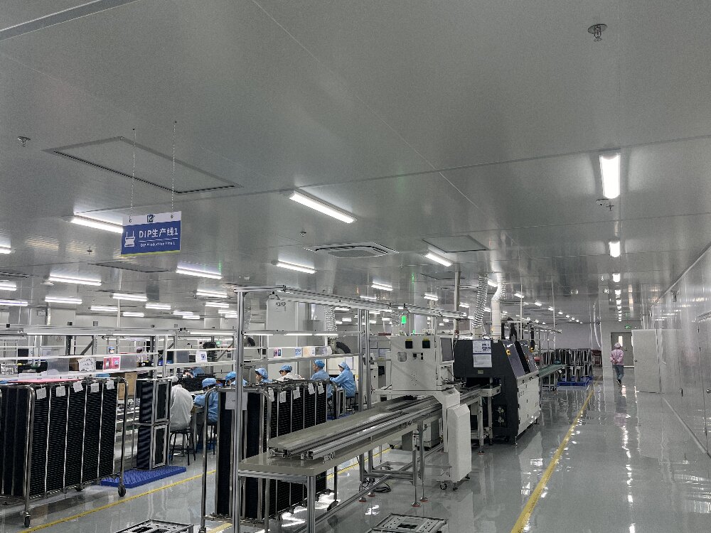
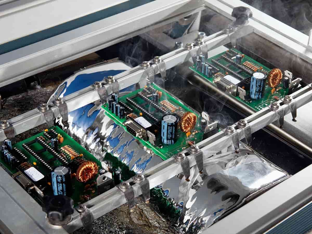
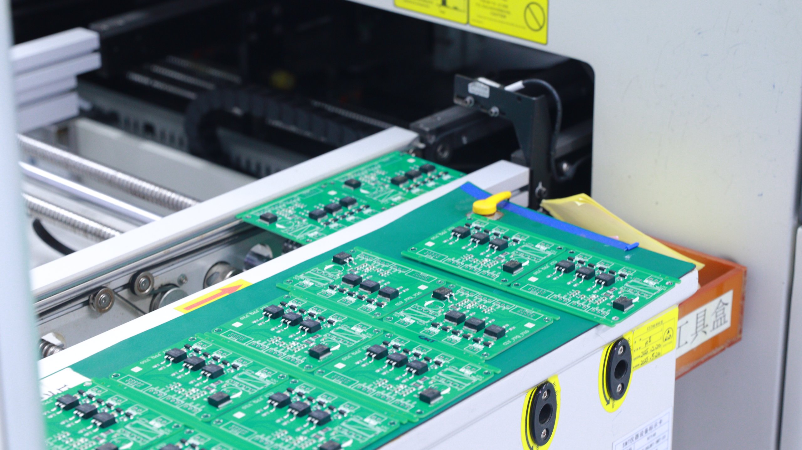
SMT manufacturing comprises four core steps: screen printing, component placement, reflow soldering and quality inspection. Each step directly impacts the reliability of the finished product. This article analyses five common quality issues—solder joint defects, component misalignment, solder paste printing defects, solder bridging and solder balls, and tombstoning—along with their solutions. It also systematically outlines the four key inspection methods—solder paste inspection, component placement inspection, soldering quality inspection and product functional testing—along with relevant considerations.

1.Basic SMT Manufacturing Process
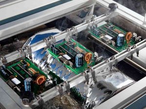
SMT manufacturing primarily comprises four steps. Screen printing involves applying solder paste to the pads on a PCB (printed circuit board), enabling components to form a secure connection with the pads via the solder paste. Placement utilises a placement machine to accurately position surface-mount devices (SMDs) onto the pads coated with solder paste. Reflow soldering involves heating the solder paste in a reflow oven to melt and solidify it, thereby securing the components in place. Quality inspection involves methods such as Automated Optical Inspection (AOI) and X-ray inspection to verify the accuracy and quality of component placement and soldering.
Each step in the above process directly affects the reliability and stability of the finished product. Particularly in high-volume production, potential quality issues during the SMT process can have a direct impact on the product’s yield rate; therefore, strict quality control and inspection are required throughout the manufacturing process.
2.Solder Joint Defects and Solutions
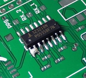
Defects include uneven solder joints, cold solder joints, cracks and solder balls. The solution is to ensure the uniformity of solder joints by controlling the solder paste thickness and printing pressure; the reflow temperature profile must be adjusted according to the components and PCB material to avoid excessively high or low soldering temperatures.
3. Component Misalignment Issues and Solutions
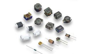
Issues include component positional misalignment or tilting, leading to poor contact or short circuits after soldering. The solution involves calibrating the placement machine and adjusting component placement accuracy during the placement stage, whilst also carrying out regular equipment maintenance to ensure the placement machine’s positioning accuracy.
4.Solder Paste Printing Defects and Solutions
Issues include uneven solder paste printing thickness and solder paste adhering to non-pad areas, which can easily lead to soldering defects. The solution is to control the squeegee pressure and speed of the screen printer, whilst checking the viscosity of the solder paste and the cleanliness of the printing stencil during operation.
5.Solder Bridging or Solder Ball Issues and Solutions
The issue involves the formation of solder bridges between adjacent solder joints, which can easily lead to short circuits. The solution is to adjust the viscosity of the solder paste and the spacing between pads, optimise the reflow soldering temperature profile, and prevent excessive overflow during the soldering process.
6.Tombstoning Issues and Solutions
This issue is characterised by one end of a small surface-mount component lifting or standing upright, resulting in poor solder joints. The solution is to control temperature fluctuations during component placement and reflow soldering to prevent uneven solder paste melting caused by thermal inconsistencies.

7. Key Points for Solder Paste Inspection
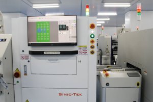
Solder paste printing is a critical stage affecting SMT quality; deviations during the printing process may lead to various defects in subsequent soldering.
Regarding print thickness, use solder paste thickness measurement instruments to check for uniformity, ensuring the strength and reliability of the solder joints. Regarding pattern integrity, observe whether the printed solder paste pattern on the pads is complete, avoiding breaks or misalignment. Regarding positional accuracy, utilise an AOI system to inspect the position of the solder paste, ensuring it fully covers the pad area.
8. Key Points for Component Placement Inspection
The position, angle and orientation of components during the placement process directly affect the success rate of soldering.
Regarding component positioning, an AOI inspection system is used to check whether placement deviations comply with standards, ensuring that all components are accurately placed on the pads. With regard to polarity and orientation, polarised components are inspected for correct polarity and orientation to prevent circuit faults caused by incorrect polarity. Regarding component integrity, the appearance of components is inspected to prevent damaged or contaminated components from entering the soldering stage.

9.Key Points for Soldering Quality Inspection
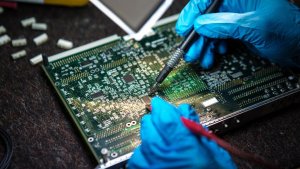
Reflow soldering is a critical curing process in SMT manufacturing; soldering quality determines the strength of the connection between components and the PCB.
Regarding solder joint shape, an ideal solder joint should form a smooth arc, with a surface free from cracks or bubbles, and uniform thickness. With regard to solder balls and solder bridges, AOI and X-ray inspection systems are utilised to detect short circuits caused by solder bridges or solder balls between joints. Regarding solder joint strength, pull tests are conducted to verify the adhesion and robustness of the joints, which is particularly applicable to components subjected to high stress.
10.Key Points for Product Functional Testing
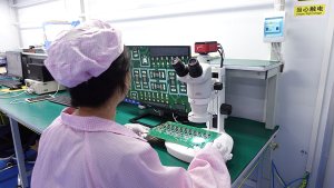
Upon completion of SMT processing, the electrical performance and functionality of the product are inspected to ensure that the circuit board operates correctly.
Short-circuit and open-circuit tests check the electrical connections on the PCB after soldering to ensure there are no short circuits or open circuits. Static and dynamic tests assess the PCB’s electrical performance under simulated operating conditions to ensure stability and reliability.
11.Production Precautions
With regard to cleaning and maintenance, screen printing stencils, placement equipment and reflow soldering equipment must be cleaned regularly during the production process to ensure equipment cleanliness and prevent contamination of the solder paste and PCB surfaces.
Regarding temperature profile settings, the reflow soldering temperature profile must be adjusted appropriately, selecting suitable temperatures based on the characteristics of different components and PCBs to prevent component damage.
With regard to equipment calibration, inspection equipment such as AOI and X-ray systems must be calibrated regularly to ensure inspection accuracy.
Conclusion
Quality control throughout the entire SMT process requires precise execution at every stage, from screen printing and component placement to reflow soldering and inspection. Only by systematically identifying common quality issues, implementing targeted solutions, establishing a multi-dimensional inspection system, and ensuring equipment maintenance and calibration can we guarantee high product yield rates and reliability, thereby winning customer trust in a highly competitive market.
