
An In-Depth Analysis of the Reflow Soldering Process in PCB Assembly
Reflow soldering is a core process in SMT and directly determines the quality of the solder joints. The setting of the temperature profile, oven temperature uniformity and atmosphere control are all critical variables. This article provides an in-depth analysis of the principles and optimisation methods of the reflow soldering process.
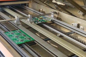
The Four Stages of Reflow Soldering
A standard reflow profile is divided into four stages: preheating, hold, reflow and cooling.
Preheating Zone: Room temperature to 150°C, with a heating rate of 1–2°C per second. Too rapid a rise causes thermal shock, whilst too slow a rise leads to premature flux evaporation.
Holding Zone: 150–183°C (lead-containing) or 150–217°C (lead-free), lasting 60–120 seconds. The flux is activated to remove oxide layers.
Reflow Zone: Above the liquidus temperature, with a peak of 235–245°C (lead-free). This forms reliable intermetallic compounds (IMCs).
Cooling Zone: Rapid cooling to room temperature at a rate of 2–4°C/second. This creates a fine-grained structure, enhancing the strength of the solder joints.
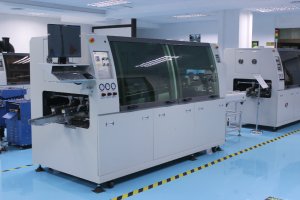
Optimisation of Temperature Profiles
Different products require customised temperature profiles.
Influencing Factors: PCB thickness, copper distribution, component density, location of heat-sensitive components, and solder paste type.
Validation Method: Measurements taken using thermocouples and a Profile Board, testing at least five representative locations (centre, edge, beneath large components, beside small components, and beneath BGAs).
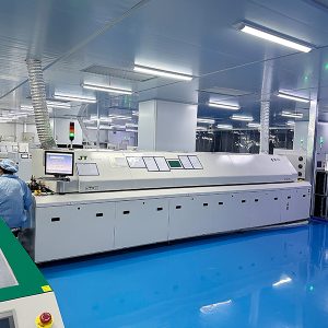
The Role of Nitrogen Protection
Nitrogen-protected reflow ovens have become standard for high-end products.
Advantages: Reduces oxidation, improves wetting, minimises voids and enhances solder joint lustre. Nitrogen purity is typically required to be 99.99% or higher.
Cost considerations: Nitrogen consumption increases operating costs; a balance must be struck between quality improvement and cost increases.
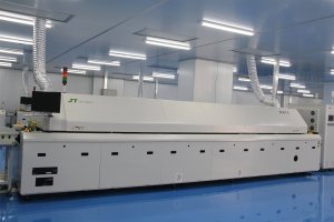
Common Temperature-Related Defects
Typical defects caused by inappropriate temperatures:
Excessively rapid preheating: Component cracking, PCB delamination
Insufficient peak temperature: Cold solder joints, cold soldering, excessively thin IMC
Excessively high peak temperature: PCB discolouration, component damage, solder balls
Excessively slow cooling: coarse grain structure, solder joint embrittlement
Excessively rapid cooling: thermal stress cracks, tombstoning
Oven Temperature Uniformity Management
Consistency across the various temperature zones of the reflow oven affects batch quality.
Maintenance key points: Regularly calibrate heating elements, clean the furnace chamber to prevent flux residue, check the stability of the conveyor belt speed, and verify the hot air circulation system.
Special challenges of lead-free reflow
Lead-free solder paste has a melting point 30°C higher, resulting in a narrower process window.
Countermeasures: Use high-Tg boards, optimise stencil aperture size to increase solder paste volume, employ nitrogen protection to reduce oxidation, and implement stricter temperature monitoring.
Reflow soldering is a process that combines experience with data. Establishing standard temperature profile profiles for each product and regularly validating oven temperature performance are fundamental to ensuring soldering consistency.
Frequently Asked Questions (FAQ)
Q1: Why should the peak temperature in reflow soldering not be too high?
A: Excessively high peak temperatures (>250°C) can lead to decomposition of the PCB substrate (expansion above the Tg), internal damage to components (such as bulging of electrolytic capacitors), and carbonised flux residues in the solder paste. Furthermore, an excessively thick IMC layer (>5μm) actually reduces the reliability of the solder joints.
Q2: What is a Profile Board?
A: A Profile Board is a specialised test board fitted with thermocouples that simulates the thermal characteristics of the actual product. The thermocouples are fixed at key positions (such as beneath BGAs or beside large components) and, as the board passes through the reflow oven on the conveyor belt, they record the actual temperature profile. This is the only reliable method for verifying reflow oven settings.
Q3: How much more expensive is a nitrogen reflow oven compared to a standard hot-air oven?
A: The equipment itself is 20–30 per cent more expensive; when combined with nitrogen consumption (approximately US$10–20 per hour), the overall operating costs increase by 15–25 per cent. However, for high-density BGAs, lead-free processes or high-reliability products, nitrogen reflow is a necessary investment.
Q4: Is it normal for PCBs to turn yellow after reflow soldering?
A: Slight yellowing (particularly after lead-free high-temperature reflow) is normal and reflects thermal ageing of the substrate and solder mask. However, severe discolouration, blistering or delamination indicates that temperatures have exceeded specifications or that the board’s Tg is insufficient; in such cases, the profile must be adjusted or the board replaced.
Q5: Can PCBs of different thicknesses be mixed in the same reflow oven?
A: This is not recommended. Differences in thickness result in varying heat capacities; thinner boards heat up quickly whilst thicker boards heat up more slowly, making it difficult to accommodate both using a single profile. If mixing is unavoidable, carriers should be used to balance the heat capacity, or a compromise profile based on a product of intermediate thickness should be selected; however, the quality of both types of board must be verified.