
Solder Paste and Reflow: The Science Behind Reliable Solder Joints
The quality of a soldered assembly is determined largely by two process steps: solder paste printing and reflow soldering. Industry studies consistently attribute 60 to 70 percent of assembly defects to issues in these stages. Understanding the science behind solder paste and reflow enables engineers to develop processes that produce reliable solder joints consistently, rather than relying on trial and error.
This article examines the materials, equipment, and process variables that determine solder joint quality, providing the technical foundation for effective process development and troubleshooting.
Solder Paste Composition and Properties
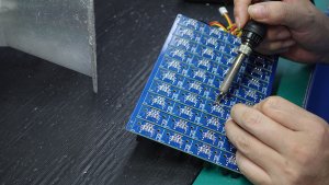
Solder paste is a homogeneous mixture of solder alloy powder and flux vehicle. The alloy powder, typically 80 to 90 percent of the paste by weight, consists of microscopic spherical solder particles. The flux vehicle provides the rheological properties that allow the paste to print through stencil apertures, hold components in place before reflow, and remove oxidation from metal surfaces during soldering.
The dominant solder alloy in modern electronics is SAC305, a tin-silver-copper alloy containing 3.0 percent silver and 0.5 percent copper. SAC305 replaced tin-lead solder following the Restriction of Hazardous Substances directive. Its higher melting point, approximately 217 degrees Celsius versus 183 for tin-lead, requires reflow profiles with higher peak temperatures. SAC alloys also have different wetting characteristics and surface tension behavior than tin-lead, affecting joint formation and self-alignment.
Particle size classification affects both printing and soldering performance. Type 3 paste, with particles ranging from 25 to 45 microns, is the standard for most SMT assembly. Type 4 paste, with smaller particles from 20 to 38 microns, is used for fine-pitch applications below 0.5mm. Type 5 and finer pastes are used for ultra-fine-pitch and dispensing applications but have shorter shelf life and higher cost.
Flux classification is equally important. No-clean flux is the most common, designed to leave benign residue that does not require removal. Water-soluble flux provides more aggressive cleaning action but requires a washing process after reflow. Rosin-based flux offers excellent wetting but may require solvent cleaning depending on the application. The flux type must be compatible with the cleaning requirements and reliability standards of the end product.

Rheology: The Science of Paste Behavior
Solder paste rheology, the study of how the paste flows under stress, directly determines printing performance. The paste must behave as a thick, cohesive material when at rest, so it does not slump or spread after printing. It must become less viscous under the shear stress of the squeegee, so it flows readily through stencil apertures. And it must return to high viscosity after printing, so it holds its shape and supports placed components.
This thixotropic behavior is achieved through careful formulation of the flux vehicle. The thixotropic index, the ratio of viscosity at low shear to viscosity at high shear, indicates how well the paste transitions between these states. A higher thixotropic index generally means better aperture release and less slumping, but may make the paste more sensitive to printing parameters.
Temperature significantly affects paste rheology. As temperature increases, viscosity decreases, which can cause slumping and bridging if the paste becomes too fluid. As temperature decreases, viscosity increases, which can cause incomplete aperture fill and insufficient paste deposition. Most paste formulations are optimized for operation at 20 to 25 degrees Celsius. Production environments must maintain this temperature range for consistent printing results.
Humidity also affects paste performance. Low humidity can cause the paste to dry, increasing viscosity and reducing printability. High humidity can cause moisture absorption, affecting flux chemistry and potentially creating soldering defects like voiding. Most paste specifications recommend 30 to 60 percent relative humidity for optimal performance.
Stencil Design: The Foundation of Print Quality
The stencil is the single most influential tool in solder paste printing. Its design determines how much paste is deposited on each pad and how consistently that deposit is maintained across the board and across production runs. Stencil design decisions made early in the NPI process affect every subsequent board produced.
Stencil thickness is the primary variable controlling paste volume. Thicker stencils deposit more paste per aperture, which is beneficial for large pads but can cause bridging on fine-pitch components. Standard thickness is 0.12mm or 0.15mm for general SMT assembly. For fine-pitch assemblies, step-down stencils with reduced thickness in fine-pitch areas allow appropriate paste volume across different pad sizes.
Aperture design determines paste deposit shape and volume. Apertures are typically laser-cut from stainless steel, with the aperture area typically equal to or slightly less than the pad area. The area ratio, the ratio of aperture opening area to aperture wall area, should be above 0.66 to ensure complete paste release from the stencil. Below this ratio, paste tends to stick to the aperture walls, resulting in insufficient deposition.
Aperture shape modifications can address specific printing challenges. Overlapping apertures for fine-pitch pads can be redesigned as individual apertures with reduced width to prevent bridging. Large pads for power components can use divided apertures, creating multiple smaller deposits that coalesce during reflow, preventing excessive paste volume while ensuring coverage. Thermal pad apertures can use a grid pattern that controls paste volume and reduces voiding during reflow.
Reflow Profile Development
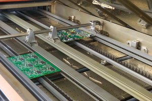
The reflow profile transforms solder paste deposits and placed components into soldered joints. The profile must heat the assembly through a carefully controlled temperature sequence that activates the flux, melts the solder, forms the joints, and cools the assembly without inducing thermal stress. Profile development is both science and art, requiring understanding of thermal dynamics and empirical optimization.
The standard reflow profile has four phases. The preheat phase raises the temperature from ambient to approximately 150 degrees Celsius at a rate of 1 to 3 degrees per second. Too fast risks thermal shock to components; too slow wastes cycle time. The preheat activates flux solvents and begins the chemical cleaning of metal surfaces.
The soak phase maintains the temperature between 150 and 200 degrees Celsius for 60 to 120 seconds. This allows the flux to fully activate, removes remaining volatiles, and equalizes temperature across the board. Adequate soak time reduces voiding by allowing flux gases to escape before the solder melts. Insufficient soak time is a common cause of high void levels in BGA joints.
The reflow phase raises the temperature above the solder liquidus point. For SAC305, the liquidus is 217 degrees Celsius. Peak temperature typically reaches 235 to 250 degrees Celsius, with time above liquidus of 30 to 90 seconds. The peak must be high enough to ensure complete solder melting and wetting but not so high as to damage temperature-sensitive components or the board laminate.
The cooling phase brings the assembly back below the liquidus point. Cooling rate affects solder joint microstructure. Faster cooling produces finer grain structure, which generally improves mechanical properties. However, cooling too fast can create thermal stress that cracks components or the board. Typical cooling rates are 1 to 4 degrees per second.
Defect Analysis and Troubleshooting
Common soldering defects can be traced to specific process stages through systematic analysis. Tombstoning, where a small passive component lifts on one end, typically indicates uneven pad heating, excessive paste on one pad, or placement offset. Solder bridging between adjacent pads usually results from excessive paste volume, paste slumping, or insufficient spacing between pads. Insufficient solder indicates low paste deposit volume, often from worn stencil apertures or incorrect squeegee parameters.
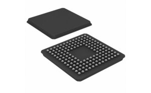
Voiding in BGA joints results from trapped flux gases, often caused by short soak times, incompatible flux formulations, or pad designs with unfilled thermal vias. Cold joints with dull, grainy appearance indicate insufficient peak temperature or inadequate time above liquidus. Component displacement after placement suggests low paste viscosity, excessive placement force, or conveyor vibration.
Effective troubleshooting requires data from multiple sources. Solder paste inspection data reveals printing trends. Reflow profile measurements verify thermal performance. Automated optical inspection identifies defect patterns. Statistical analysis of defect data by type, location, and frequency points to the process stage where correction is needed. A PCB assembly manufacturer with robust process monitoring capabilities can identify and correct these issues quickly, maintaining high yields. Partnering with a technically capable PCBA service that invests in process engineering expertise ensures that solder paste and reflow processes are developed scientifically, not by trial and error.