

Solderability testing measures how willingly molten solder wets a component termination, a plated through-hole, or a bare board pad under controlled conditions. It is the cheapest insurance policy in PCB assembly, and it is the step most often skipped when schedules tighten. A part that wets poorly will still be placed, still pass through reflow, and still look plausible on the line — then crack open in the field eighteen months later. Solderability testing exists to pull that failure forward to incoming inspection, where it costs a reel instead of a recall.
The subject deserves more attention than it gets because it sits upstream of every other process control. Stencil design, reflow profile, and AOI programming all assume the surfaces they touch are wettable. When they are not, the process engineer spends a week chasing a defect that was decided by a plating bath months earlier.
Solderability Describes the Surface’s Willingness to Be Wetted
Wetting is a surface-energy event. For solder to spread and bond, its surface tension must be overcome by the affinity between the molten alloy and the base metal. Flux removes the oxide layer that blocks that contact; once the oxide is gone, the alloy dissolves a thin layer of the termination and forms an intermetallic compound such as Cu6Sn5 at the interface. A properly wetted joint shows a contact angle below roughly 90 degrees and a concave fillet that feathers toward the pad edge.
Three variables decide whether that happens: the base metal, the protective finish over it, and everything the part has been exposed to since plating. A copper lead with a fresh tin finish wets in under a second. The same lead after six months in a humid warehouse, still inside its original bag, may dewet into isolated droplets. Nothing about the part’s specification changed — only its history.
Solderability is not the same property as solder paste quality. Paste is characterised by viscosity, slump, tack, and metal content under J-STD-005. Solderability testing concerns the surfaces being joined, which is why the two are specified, sampled, and rejected separately.

The Wetting Balance Test Puts a Number on Solderability
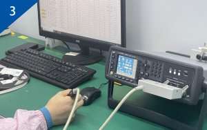
The wetting balance, or meniscograph, is the quantitative reference method. A specimen is suspended from a sensitive load cell and dipped into a solder pot at a fixed speed, depth, and temperature. The instrument records force against time from the instant of immersion.
The resulting curve is read through three values. Zero crossing time, often written T0, is when the wetting force overcomes buoyancy. T2 is the time to reach two thirds of maximum wetting force. Fmax is the peak force itself. Short T0 and high Fmax indicate an active, clean surface; a curve that never crosses zero indicates a surface that will not wet at all. IPC J-STD-002 Test A compares these values against a reference curve generated from a known-good control, and a lot fails when it reaches two thirds of the reference force too slowly.
The practical value of the wetting balance is trend detection. Because it returns numbers rather than opinions, it catches a plating line drifting out of specification before visual inspection can see anything wrong. That makes it the right tool for supplier qualification and for monitoring a plating process over time.

Dip-and-Look Testing Remains the Production Workhorse
Most high-volume plants run dip-and-look testing daily because it is fast, inexpensive, and needs no capital equipment beyond a temperature-controlled pot. Terminations are fluxed, dipped into solder for about five seconds, and examined under magnification for coverage and fillet shape.
The preconditioning step is what gives the test its meaning. Freshly plated parts wet almost regardless of process control, so samples are usually steam aged for eight hours at 93 degrees Celsius and about 95 percent relative humidity to simulate a year or more of shelf life. Only aged parts reveal whether the finish has enough margin. Dip temperature and duration follow J-STD-002 conditions selected for the alloy and the part’s heat resistance.

Acceptance is commonly set at 95 percent continuous coverage of the termination, with no dewetting and with pinholes tolerated only if they are small and scattered rather than clustered. The weakness of the method is subjectivity, which is why audited programs keep a reference photo library and rotate operators through a yearly correlation exercise.
Board Finish and Storage History Set the Solderability Window
Bare board pads face the same physics and a harder schedule, because the finish must survive fabrication, shipping, paste printing, and often two or three reflow passes on the second side. Each finish trades shelf life against planarity, cost, and failure mode.
| Surface finish | Typical shelf life | Solderability strength | Characteristic risk |
|---|---|---|---|
| Hot air solder levelling | 12 months or more | Very robust, thick solderable layer | Non-planar pads limit fine-pitch printing |
| Immersion silver | 6 to 12 months | Excellent wetting, flat surface | Tarnishes with sulfur exposure, cosmetic rejects |
| Immersion tin | 6 months | Good, flat, suited to fine pitch | Oxide growth and tin whisker risk over time |
| OSP | 6 to 12 months | Adequate for one or two reflow cycles | Degrades after multiple heat excursions |
| ENIG | 12 months | Excellent, very flat, long storage | Black pad from nickel corrosion if the bath drifts |
ENIG deserves a note because its failure mode is deceptive. When the nickel layer is over-attacked during immersion gold plating, the resulting phosphorus-rich surface wets unevenly and produces brittle joints that pass visual inspection. Thickness control, bath analysis, and a solderability check on every new panel lot are the only reliable defenses.

Shelf Life, Packaging and Handling Quietly Destroy Solderability
Oxidation is a function of time, temperature, humidity, and contaminants. Sulfur from cardboard cartons, chlorine from improperly cured packaging, and humidity cycling inside a warehouse all accelerate the growth of oxide and corrosion products on a finish that was perfectly good when it shipped.
The controls are unglamorous but effective. Keep moisture-sensitive and solderability-sensitive parts in dry cabinets purged with nitrogen, respect sealed-bag integrity, apply strict first-in-first-out rotation against date codes, and log every time a reel is opened. Parts returned from a cancelled build should be re-tested rather than automatically returned to stock.
One misconception is worth correcting: baking a part does not restore solderability. Baking drives off moisture absorbed during exposure, which is what J-STD-033 addresses, but the same heat accelerates intermetallic growth and surface oxidation. A part that fails a wetting test because of oxide will still fail after baking, and may fail worse. In practice, how a PCB assembly manufacturer stores incoming parts matters more to final yield than the finish named on the drawing.

Failure Signatures Point Directly at the Root Cause
Reading a failed sample correctly saves more time than running the test. Each signature maps to a narrow set of causes, and the map is worth memorising.
- Non-wetting: solder balls up and the base metal stays visible. Usually gross oxide, oil or silicone contamination, or a finish too thin to protect the underlying metal.
- Dewetting: solder initially covers the surface, then recedes into droplets leaving a thin residue. Points to contaminated plating, excessive intermetallic growth from over-ageing, or insufficient flux activity.
- Pinholes: scattered voids in an otherwise wetted area. Often gas evolution from contaminated plating or from organic residues burning off.
- Uneven, grainy coverage on ENIG: the classic black pad signature, caused by nickel corrosion during gold deposition.
- Leaching: the termination dissolves into the solder, thinning the joint. Typical of gold-plated leads without a nickel barrier.
Because these signatures overlap, a failure should always be confirmed with a cross-section or a plating thickness measurement before a supplier is charged with a nonconformance.
Incoming Inspection Turns Solderability Testing Into a Supplier Metric
The test only changes behaviour when its results are recorded, trended, and attached to a supplier name. A workable programme samples each part number at first receipt, then on a defined frequency such as one lot per part per quarter, and immediately after any change of plating source, packaging, or storage duration beyond the finish’s rated shelf life.
Results belong in the same database as first pass yield, so that a wetting time creeping upward can be correlated with a slow rise in mid-volume solder defects. When a lot fails, the response should be a documented supplier corrective action request with a returned sample and a request for the plater’s bath records, not simply a rejected carton.
The economics are lopsided. Rejecting one reel of 5,000 connectors costs a few hundred dollars and a phone call. Discovering the same problem after those connectors are on 5,000 boards costs rework labor, scrapped assemblies, expedited replacement parts, and a delivery commitment that has already been broken.
Different Component Families Need Different Solderability Tests
Test geometry has to match termination geometry, which is why J-STD-002 defines several methods rather than one. Chip components are dipped and inspected on all three termination faces. Gull-wing and J-lead parts are dipped to a controlled depth so the foot, heel, and side fillet can each be judged. Area array packages with solder balls are evaluated by a sphere wetting method that looks at collapse and spread rather than a fillet.
Through-hole and press-fit parts split the question differently. Press-fit pins are not soldered at all, so their qualification concerns insertion force and plating durability rather than wetting. Flexible circuits combine a pad wetting check with a heat resistance check, because polyimide delamination can fail a board that wets perfectly.
The common thread is that a single pass or fail statement is not enough. The test record should name the method, the preconditioning applied, the alloy and temperature used, and the acceptance criterion — otherwise two plants can report opposite results on identical parts and both be technically correct. A one-stop PCBA solution provider should be able to produce that record on request for any part on the BOM.
Summary
Solderability testing answers one question before production commits: will these surfaces actually bond? The wetting balance gives a numeric, trendable answer suitable for supplier qualification, while dip-and-look testing supplies a fast daily screen when preconditioned with steam ageing. Board finish choice, storage discipline, and packaging hygiene set the window in which any of that matters, and baking is not a repair for oxidation. Read failure signatures carefully, record results per supplier and part number, and the test stops being a paperwork exercise and becomes an early warning system for the entire assembly line.
FAQ
How often should solderability testing be performed?
At minimum, test every new part number on first receipt and every lot after a plating source change or an extended storage period. Mature part numbers are commonly re-tested quarterly, or whenever a related defect trend appears in assembly yield data.
Does a passed solderability test guarantee a good joint?
No. It confirms the surfaces can be wetted under defined conditions. Joint quality still depends on paste volume, reflow profile, component co-planarity, and thermal mass, all of which are separate process controls.
Can oxidized components be recovered instead of scrapped?
Occasionally, with an approved re-tinning or a more active flux evaluated through a full reliability qualification. In most cases the safer decision is to reject the lot, because recovered terminations often carry thicker intermetallics and a shorter fatigue life.