
FR-4, Rogers, Metal Core, and Ceramic Substrates Explained
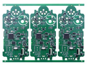
The PCB substrate is the foundation upon which every electrical connection, thermal path, and mechanical structure depends. Choosing the wrong material causes signal integrity failures, thermal damage, or cost overruns that cannot be fixed in assembly. At Keep best, our engineering team reviews substrate selection during DFM to prevent these problems before fabrication begins. FR-4 dominates consumer electronics because it is inexpensive and well-understood. But when frequency rises, power increases, or reliability requirements tighten, engineers must consider Rogers, metal-core, and ceramic alternatives. This guide explains the properties, trade-offs, and manufacturing implications of each material family.
FR-4: The Workhorse Substrate
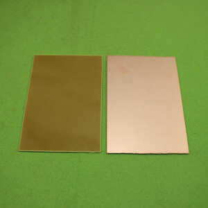
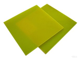
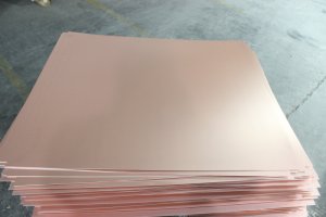
FR-4 is a composite of woven fiberglass cloth and epoxy resin, designated flame-retardant per UL94V-0 standards. It accounts for approximately 90 percent of all PCB production worldwide.
Electrical Properties: Standard FR-4 has a dielectric constant of approximately 4.3 at 1 megahertz and a dissipation factor of 0.02. These values vary with resin content, glass weave style, and measurement frequency. For general digital designs below 1 gigahertz, FR-4 performs adequately. At higher frequencies, the dielectric constant variation across the glass weave causes impedance non-uniformity known as the glass weave effect.
Thermal Properties: FR-4 has a glass transition temperature between 130 and 180 degrees Celsius depending on formulation. Standard FR-4 begins to soften and degrade near its Tg. High-Tg variants with Tg above 170 degrees Celsius resist thermal stress better during lead-free reflow and high-temperature operation. Thermal conductivity of FR-4 is poor at approximately 0.3 watts per meter-kelvin, which limits heat spreading from hot components.
Mechanical Properties: FR-4 offers good mechanical strength, machinability, and dimensional stability. It is compatible with standard drilling, routing, and plating processes. Multilayer construction is straightforward up to 20 or more layers. The material is widely available from multiple suppliers in standard thicknesses from 0.1 to 3.2 millimeters.
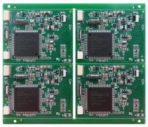
When to Use FR-4: FR-4 is the correct choice for consumer electronics, industrial control systems, automotive body electronics, and any application where cost is a primary driver and operating frequencies remain below a few hundred megahertz. It is also suitable for moderate-power applications where thermal management is handled through component-level heat sinks rather than board-level conduction.
High-Performance FR-4 Variants
Modern electronics have pushed FR-4 technology to evolve beyond the basic formulation.
Low-Dk and Low-Df FR-4: Advanced epoxy systems reduce dielectric constant to approximately 3.5 and dissipation factor to 0.009. These materials approach the performance of Rogers at a fraction of the cost. They are suitable for 5 gigahertz and 10 gigahertz digital designs, automotive radar, and basic RF applications. Leading examples include Panasonic Megtron 6, Isola I-Speed, and Shengyi S1000-2.
Halogen-Free FR-4: Environmental regulations in Europe and Asia restrict halogenated flame retardants. Halogen-free FR-4 uses phosphorus and nitrogen compounds instead of bromine. Electrical properties are comparable to standard FR-4, but the material is slightly more hygroscopic and requires adjusted process parameters during lamination.
Filled and High-Resin Systems: Filling the epoxy matrix with ceramic particles improves thermal conductivity to 0.5 to 0.8 watts per meter-kelvin. These materials spread heat better than standard FR-4 without the cost of metal-core boards. They are popular for LED lighting and medium-power converters.
Rogers and High-Frequency Laminates
When signal integrity demands exceed FR-4 capabilities, ceramic-filled PTFE or thermoset laminates provide the answer.
PTFE-Based Materials: Rogers RT/duroid and Taconic TLY series use polytetrafluoroethylene with ceramic fillers. These materials offer dielectric constants from 2.2 to 10.2 with extremely low dissipation factors below 0.002. They are the standard for microwave and millimeter-wave circuits including 5G base stations, satellite communications, and automotive radar.
Thermoset High-Frequency Materials: Rogers RO4000 series uses thermoset hydrocarbon ceramic systems rather than PTFE. These materials are process-compatible with standard FR-4 fabrication, including through-hole plating and multilayer lamination. Dielectric constant is stable across temperature and frequency. RO4350B with Dk of 3.48 is widely used for 24 gigahertz and 77 gigahertz radar modules.
Manufacturing Considerations: Rogers materials require process adjustments. PTFE laminates need plasma or sodium etching for through-hole plating adhesion. Drill parameters differ from FR-4 due to softer material properties. Registration tolerances may be tighter for multilayer constructions. PTFE also exhibits higher thermal expansion, which challenges plated through-hole reliability under thermal cycling.
Cost Impact: Rogers materials cost 5 to 20 times more than FR-4 per square meter. The total board cost impact depends on layer count, panel utilization, and fabrication complexity. For high-frequency designs, the material cost is justified by performance. For cost-sensitive consumer products, using Rogers for only critical RF layers in a mixed stackup reduces expense.
Metal-Core PCBs
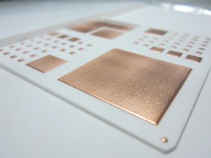
Metal-core PCBs use aluminum or copper as the substrate instead of fiberglass. The metal provides exceptional thermal conductivity for applications where heat must be removed efficiently.
Structure: A typical aluminum-core PCB consists of a 1.0 to 3.0 millimeter aluminum plate, a thin dielectric layer of 75 to 150 microns, and a single or double-sided copper circuit layer. The dielectric is thermally conductive epoxy or polyimide filled with ceramic particles.
Thermal Performance: Aluminum thermal conductivity is approximately 150 to 200 watts per meter-kelvin. Copper reaches 400 watts per meter-kelvin. This is 500 to 1,000 times better than FR-4. LED applications with high-power chips mounted directly on the metal core achieve junction temperatures 20 to 40 degrees Celsius lower than equivalent FR-4 designs.
Electrical Isolation: The thin dielectric layer provides electrical isolation between the circuit and the metal base. Breakdown voltage typically exceeds 3 kilovolts. For high-voltage applications, thicker dielectrics or multiple isolation layers may be required. The dielectric thermal resistance limits overall thermal performance, so material selection here is critical.
Single vs Double Sided: Single-sided metal-core boards are simplest to manufacture. Double-sided boards require through-hole insulation because the metal core shorts all vias. This is achieved with insulated metal substrates or selective removal of the core around via barrels. Both approaches add cost and complexity.
Manufacturing Challenges: Metal-core boards cannot use standard multilayer lamination because the metal base does not bond with prepreg. Multilayer metal-core constructions require special adhesives, riveting, or separate PCB sections mounted on the metal plate. Routing and machining aluminum requires carbide tooling rather than standard PCB routers.
Applications: LED lighting, power supplies, motor drives, and automotive lighting are the primary applications. Any design where a component dissipates more than 2 watts and cannot tolerate a hot spot benefits from metal-core construction.
Ceramic Substrates
Ceramic PCBs use alumina, aluminum nitride, or silicon carbide as the base material. These substrates offer the ultimate combination of thermal conductivity, electrical insulation, and high-temperature operation.
Alumina Al2O3: Alumina is the most common ceramic substrate. It offers thermal conductivity of 20 to 30 watts per meter-kelvin, dielectric constant of 9.5, and excellent mechanical strength. It is compatible with thick-film and thin-film metallization. Alumina is used in high-power RF amplifiers, LED packages, and automotive sensors.
Aluminum Nitride AlN: AlN provides thermal conductivity of 140 to 230 watts per meter-kelvin, approaching copper while maintaining electrical insulation. This makes it ideal for power modules, IGBT packages, and high-brightness LED arrays where heat must spread rapidly across the board. AlN is more expensive than alumina and requires specialized fabrication processes.
Silicon Carbide SiC: SiC substrates operate at temperatures exceeding 500 degrees Celsius. They are used in extreme environments such as aerospace propulsion systems and downhole oil exploration electronics. SiC is expensive and difficult to machine, limiting use to specialized applications.
Direct Bonded Copper: DBC technology bonds copper foil directly to ceramic substrates. The copper provides high-current traces with low resistance while the ceramic insulates electrically and conducts heat. DBC is the standard for power module substrates in electric vehicles and renewable energy inverters.
Manufacturing: Ceramic substrates are fabricated using laser machining, screen printing, and firing rather than standard PCB etching. Via formation uses laser drilling. Metallization uses thick-film paste firing or thin-film sputtering. Assembly requires specialized solder pastes and profiles due to the high thermal mass of ceramic.
Material Comparison Summary
| Property | Standard FR-4 | High-Tg FR-4 | Rogers RO4350B | Aluminum Core | Alumina Ceramic |
| — | — | — | — | — | — |
| Dk at 1 GHz | 4.3 | 4.3 | 3.48 | N/A | 9.5 |
| Df at 1 GHz | 0.02 | 0.015 | 0.0037 | N/A | 0.0002 |
| Thermal conductivity W/mK | 0.3 | 0.3 | 0.6 | 150-200 | 20-30 |
| Tg C | 130-140 | 170-180 | >280 | N/A | >1000 |
| Max operating temp C | 130 | 170 | 280 | 150 | 500+ |
| Relative cost | 1x | 1.3x | 5-10x | 2-4x | 10-50x |
| Typical layers | 1-20+ | 1-20+ | 1-6 | 1-2 | 1-2 |
Hybrid and Mixed Stackups
Complex designs often combine materials in a single board to optimize cost and performance.
Mixed FR-4 and Rogers: A common approach places Rogers laminate on outer layers for RF circuits while using FR-4 for internal digital and power layers. This requires compatible prepregs for lamination and careful impedance modeling across material transitions. The stackup must account for different coefficients of thermal expansion to prevent delamination.
Metal Core with FR-4 Overlay: For products requiring both high-power LED circuits and complex control electronics, a metal-core section handles thermal management while a separate FR-4 section carries the processor and memory. The two sections connect through board-to-board connectors or flexible jumpers.
Ceramic with Organic Overlay: Some power modules use ceramic DBC for the power stage and laminate an organic PCB on top for control circuits. This combines the thermal performance of ceramic with the multilayer capability and component density of standard PCB technology.
Selecting the Right Material
Material selection should be driven by electrical, thermal, and mechanical requirements rather than habit or cost alone.
Electrical Requirements: For frequencies above 1 gigahertz, evaluate dielectric constant stability and dissipation factor. FR-4 is adequate below 500 megahertz. Low-Dk FR-4 extends this to 3 to 5 gigahertz. Rogers is necessary for 10 gigahertz and above or where phase stability is critical.
Thermal Requirements: Calculate the thermal resistance path from junction to ambient. If the board contributes more than 20 percent of total thermal resistance, consider metal-core or ceramic. For LED applications, junction temperature directly impacts lumen maintenance and lifetime. Every 10 degrees Celsius reduction doubles expected life.
Mechanical Requirements: Flexible and rigid-flex circuits require polyimide substrates rather than FR-4. High-vibration applications benefit from ceramic or metal-core materials because they resist board flexing that fatigues solder joints.
Cost and Supply Chain: Exotic materials have longer lead times and limited supplier bases. Always confirm material availability with your fabricator before finalizing the design. For high-volume products, negotiate material stocking agreements to prevent production delays.
Frequently Asked Questions
Q: Can you manufacture mixed stackup boards with FR-4 and Rogers layers?
Yes. Keep best supports hybrid multilayer constructions combining Rogers high-frequency laminates with standard FR-4 cores. Our engineering team models impedance transitions across material boundaries and verifies lamination compatibility before fabrication.
Q: What is the minimum order quantity for metal-core PCBs?
We support metal-core prototype quantities from 10 pieces. Volume production of 1,000 pieces or more achieves optimal pricing. Aluminum-core single-sided boards are most economical. Double-sided and multilayer metal-core constructions require higher volumes to justify tooling.
Q: Do ceramic substrates support surface-mount assembly?
Yes. Ceramic PCBs accept standard SMT components with adapted solder profiles. The high thermal mass of ceramic requires longer preheat and slower ramp rates to prevent thermal shock. We develop custom profiles for ceramic assemblies based on substrate thickness and component mix.
Q: Can I use standard FR-4 for a 2.4 gigahertz wireless design?
Standard FR-4 is marginal at 2.4 gigahertz. The design may work but antenna efficiency and trace loss will suffer compared to low-Dk materials. For cost-sensitive consumer products with integrated antennas, low-Dk FR-4 variants offer a good compromise. For external antennas or long traces, Rogers provides more consistent performance.
Q: How does material choice affect PCB lead time?
Standard FR-4 ships within 5 to 10 days. Rogers materials may require 2 to 4 weeks due to limited distributor stock. Ceramic substrates often need 4 to 6 weeks because they are made to order. Plan material selection early in the project to avoid schedule impact.
Conclusion
Material selection is a systems-level decision that affects electrical performance, thermal management, mechanical reliability, and total cost. FR-4 serves most applications well. Rogers extends performance into microwave frequencies. Metal-core solves thermal challenges. Ceramic substrates handle the most extreme environments. The right material is the one that meets all requirements at the lowest total cost of ownership.
Send your design requirements to the Keepbest engineering team. We will evaluate your electrical, thermal, and mechanical requirements, recommend the optimal substrate material, and provide design guidelines that ensure manufacturability and performance.