
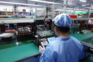
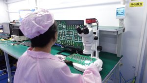
Functional testing (FCT) is the final quality control step before PCB assemblies are shipped. Unlike ICT, FCT verifies the actual functionality of the circuit rather than the parameters of individual components. This article analyzes the key design considerations and implementation strategies for FCT.
Differences Between FCT and ICT
ICT (In-Circuit Testing) checks component values and solder joint quality and requires access to test points. FCT (Functional Testing) simulates real-world operating conditions to verify circuit functionality.
Key Comparisons: ICT coverage is limited by test points; FCT requires test fixtures and programs; the two are complementary and cannot replace each other.
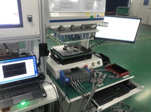
Test Fixture Design
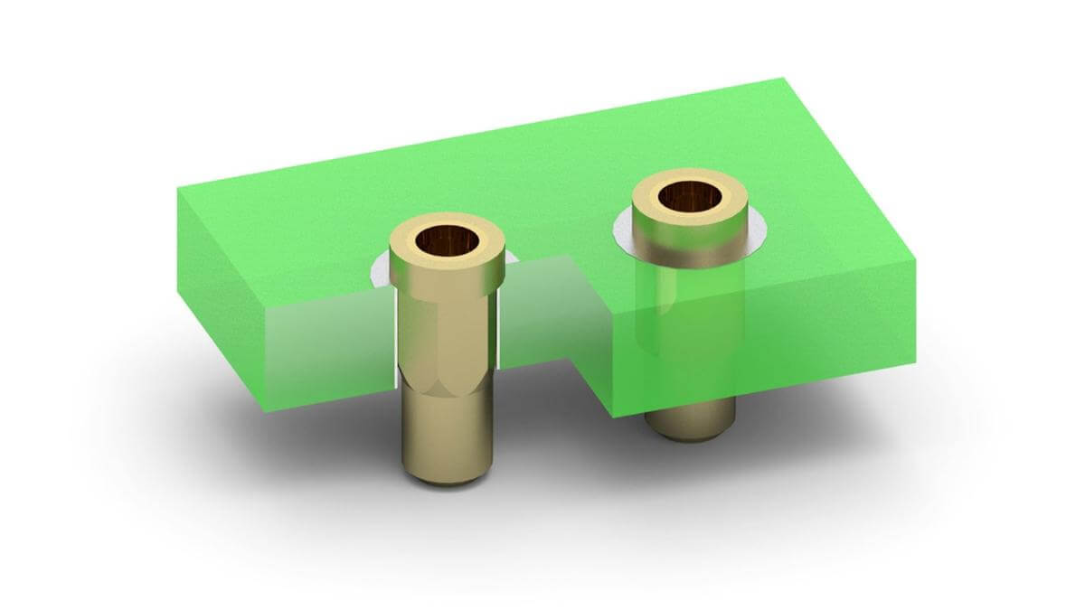
The test fixture serves as the hardware foundation for FCT.
Design Elements: Probe selection (spring pins or pogo pins), positioning accuracy (±0.05 mm), clamping mechanism (pneumatic or manual), and interface connection (for communication with the tester).
Cost Control: Pin-bed fixtures are suitable for high-volume production, while flying probe fixtures are suitable for small batches but are slower.

Test Program Development
The test program determines the depth of coverage for FCT.
Development Process: Requirements analysis (which functions to test), use case design (normal/boundary/abnormal conditions), program writing (LabVIEW or C), and verification and debugging.
Key Metrics: Test time (affects production capacity), false positive rate (requires manual retesting), coverage rate (percentage of functional points tested).
Boundary Scan Testing
Traditional ICT struggles to cover high-density BGA boards. Boundary scan (JTAG) provides an alternative solution.
Applicable Scenarios: FPGA/CPLD configuration verification, flash memory programming tests, board-to-board interconnect testing.
Implementation Requirements: Reserve a JTAG interface during PCB design; chips must support the IEEE 1149.1 standard.
Environmental Stress Testing
Some products require simulation of harsh environments.
Test Types: High-low temperature cycling (-40°C to 85°C), humidity testing (85% RH), power fluctuation testing, and EMC pre-testing.
Test Data Management
FCT data serves as a critical basis for quality traceability.
Management Scope: Test results (Pass/Fail), test parameters (voltage/current/waveforms), anomaly records, and integration with the MES system.
FCT strategies must be planned during the product design phase. Reserving test interfaces, planning test point layouts, and collaborating with PCB assembly factories on fixture design can significantly reduce testing costs later in the process.

Frequently Asked Questions (FAQ)
Q1: Which is more important, FCT or ICT?
A: The two are complementary. ICT detects soldering and component issues (manufacturing defects), while FCT detects functional and performance issues (design defects). Ideally, both should be performed; however, when budgets are limited, prioritize FCT for complex products and ICT for simple products.
Q2: How much does an FCT test fixture cost?
A: A probe bed fixture typically costs $500–$3,000, depending on the number of probes and complexity. Flying probe testing does not require fixtures but takes longer. For small batches (<<100 units), generic fixtures or manual testing can be used as alternatives to custom fixtures.
Q3: How do you design a PCB that is easy to test?
A: Reserve test points (diameter ≥0.8 mm), route critical signals to the test interface, ensure easy access to power and ground lines, and avoid having test points obscured by components. Communicate with the factory’s test engineers early on to understand their fixture capabilities.
Q4: Can boundary scan (JTAG) replace ICT?
A: It cannot fully replace it. JTAG excels at testing digital circuit interconnections and programming, but it cannot test analog circuits, power integrity, or RF performance. The best practice is a combination of JTAG and partial functional testing.
Q5: What is a reasonable FCT test duration?
A: For consumer electronics, it is typically 30–60 seconds per board; for industrial control, 2–5 minutes; and for automotive electronics, it may exceed 10 minutes. Test duration directly impacts production capacity, so a balance must be struck between coverage and efficiency. Parallel testing and multi-station fixtures can improve efficiency.