

Rigid PCBs have served the electronics industry for decades, but modern products demand shapes and form factors that flat boards cannot achieve. Medical endoscopes must thread through curved anatomical paths. Wearable devices must conform to wrists and skin. Aerospace instruments must fold into tight avionics bays. These applications require flexible circuits — and the specialized manufacturing discipline to assemble them reliably. At Keepbest, we assemble rigid-flex and pure flex PCBAs for customers who cannot compromise on reliability in dynamic mechanical environments.
This guide explains the unique challenges of flex and rigid-flex assembly, what process controls are essential, and how to design for manufacturability in flexible electronics.
What Is Flex PCBA?
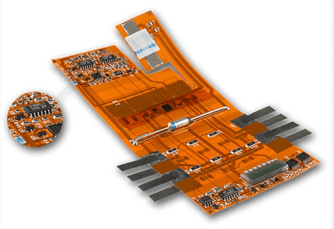
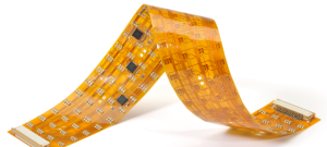
A flexible printed circuit is built on polyimide or polyester substrate instead of rigid FR-4. The substrate bends, folds, and flexes without cracking copper traces, enabling electronics to fit into non-planar geometries.
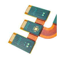
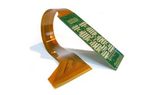
A rigid-flex circuit combines rigid PCB sections with flexible interconnects in a single laminated structure. Rigid sections carry dense component layouts while flexible sections provide mechanical articulation or space-saving folds.
| Attribute | Rigid PCB | Flex Circuit | Rigid-Flex |
| Substrate | FR-4 glass epoxy | Polyimide (Kapton) | Combined FR-4 and polyimide |
| Bending capability | None | Repeated dynamic flexing | Limited flex sections |
| Component mounting | Both sides possible | Typically one side | Rigid sections only |
| Weight | Higher | 70-90% lighter | Intermediate |
| Cost | Lowest | Moderate | Highest |
| Applications | Standard electronics | Dynamic flex, tight spaces | Complex 3D geometries |
Unique Assembly Challenges
Mechanical Handling: Flex circuits are thin, lightweight, and easily damaged by tension, compression, or sharp bends during assembly. Standard conveyor belts and board supports designed for rigid boards can wrinkle, crease, or tear flex substrates.
Thermal Management: Polyimide has different thermal conductivity and expansion characteristics than FR-4. Reflow profiles must be adjusted to prevent delamination at rigid-flex transition zones.
Component Placement: Components are mounted only on rigid sections. The flexible portion must remain free of components to preserve bend capability. Placement machines require specialized fixtures that support rigid sections while allowing flexible sections to hang freely.
Solder Joint Reliability: Flex circuits experience mechanical stress during bending. Standard solder joints can crack under repeated flexure. Underfill, corner bonding, or flexible solder alloys may be required for high-reliability applications.
Your manufacturing partner Flex and Rigid-Flex Capabilities
Specialized Fixturing: Custom magnetic and vacuum fixtures support rigid sections during printing, placement, and reflow while allowing flexible sections to remain unconstrained. Fixturing is designed per panel to match the specific rigid-flex geometry.
Reflow Profile Development: Thermocouples are placed at rigid-flex junctions to monitor temperature gradients. Profiles are optimized to prevent delamination while achieving full solder wetting.
Adhesive Reinforcement: Structural adhesive is applied at rigid-flex transition zones to prevent stress concentration and cracking during flexure. Adhesive type is selected for the application’s temperature range and flex cycle count.
Bend Radius Verification: Post-assembly bend testing validates that the completed assembly meets the minimum bend radius specification without trace cracking or delamination.
Design for Manufacturability: Flex and Rigid-Flex
Component Placement: Place all components on rigid sections. Maintain a 3 mm keepout zone from the rigid-flex transition line to allow adhesive fillets and prevent solder wicking onto the flex.
Via and Hole Placement: Avoid plated through holes in the flex section if possible. If necessary, use microvias or blind vias that do not create stress concentrators. Vias at the rigid-flex boundary are particularly vulnerable to cracking.
Copper Distribution: Balance copper coverage across the flex section to prevent warpage. Uneven copper distribution causes the flex to curl, complicating assembly and integration.
Coverlay vs. Solder Mask: Flex circuits use coverlay (polyimide film with adhesive) rather than liquid solder mask because coverlay flexes without cracking. Ensure coverlay openings are properly aligned with pads and do not encroach on transition zones.
Stiffeners: Add polyimide or FR-4 stiffeners to flex sections that require component attachment or connector insertion. Stiffeners prevent tearing during connector mating and provide mechanical support for localized component mounting.
Testing and Reliability Validation
Electrical Testing: Continuity and isolation testing verifies that traces remain intact after assembly and any required bending. High-potential testing confirms insulation integrity between layers.
Thermal Cycling: Subject assemblies to repeated temperature excursions to validate solder joint reliability at rigid-flex junctions. Typical profiles range from -40°C to +125°C for 500 to 1000 cycles.
Flex Endurance Testing: For dynamically flexed applications, subject sample assemblies to the specified bend radius and cycle count. Monitor for resistance changes, intermittent opens, and visual damage.
Frequently Asked Questions
Q: What is the minimum bend radius for a flex circuit?
The minimum bend radius depends on copper thickness, layer count, and whether the bend is static or dynamic. A common rule is six times the total circuit thickness for static bends and twelve times for dynamic repeated flexing.
Q: Can components be mounted on the flexible portion?
Generally no. Components mounted on flex sections create stress concentrators and restrict bending. If component mounting on flex is absolutely necessary, use stiffeners and specialized low-stress attachment methods.
Q: How much more expensive is rigid-flex compared to rigid PCB?
Rigid-flex typically costs 3 to 5 times as much as an equivalent rigid PCB due to specialized materials, lower manufacturing yields, and complex lamination processes. The cost is justified when product form factor or reliability requirements demand it.
Q: What industries use rigid-flex PCBAs most?
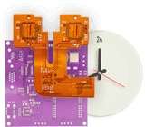
Medical devices (endoscopes, hearing aids, patient monitors), aerospace (avionics, satellites), consumer electronics (foldable phones, wearables), and automotive (instrument clusters, camera modules).
Q: How do I specify stiffener requirements?
Include stiffener material, thickness, location, and adhesive type in your fabrication drawing. Specify whether stiffeners are bonded on one side or encapsulated. Keepbest reviews stiffener designs for manufacturability during DFM.
Q: Can The EMS provider prototype rigid-flex designs?
Yes. We support prototype quantities from 5 units for design validation, through pilot production, to mass production with process controls matched to volume. The same engineering team handles all phases.
Designing a flex or rigid-flex product? Send your mechanical constraints, bend radius requirements, and electrical specifications to the Keepbest rigid-flex engineering team. We will review your design for manufacturability and propose an assembly approach matched to your reliability goals.