
Defects in PCBA manufacturing and rework often arise due to soldering, components, materials, or design factors. This article outlines five common types of rework issues, analyzes their causes, and provides practical solutions to help production lines quickly identify problems and reduce rework costs.
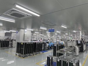
Five Typical Issues to Focus on in PCBA Rework
PCBA rework issues primarily fall into five categories: soldering, components, residue, circuit boards, and electrical performance. Accurately identifying the root causes of each issue is essential for developing effective rework solutions. Below, we break down the symptoms, causes, and countermeasures for each category.
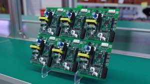
Soldering Defects Are the Most Common Re-work Issue
Soldering defects include cold solder joints, cold solder, bridging, and abnormal solder joint morphology, which can lead to poor contact or even short circuits. Causes include solder paste with substandard metal content, improper reflow temperature profile settings, and insufficient or inaccurate solder paste dispensing. To resolve these issues, optimize the reflow soldering temperature profile based on the characteristics of the PCB and components to ensure complete metallic bonding at the solder joints; use high-quality, standard solder paste within its expiration date; and regularly calibrate the screen printer and placement machine to ensure accurate solder paste volume and placement, thereby reducing bridging and cold solder joints at the source.
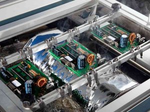
Component Damage Stems from Uncontrolled Pressure and Temperature
Component damage during rework or processing manifests as bent leads, surface scratches, and other issues; in severe cases, components may be rendered completely unusable. Common causes include improper pressure from the placement machine’s grippers, manual handling errors, and thermal damage resulting from poor temperature control. Corresponding measures include adjusting placement machine parameters to ensure moderate placement pressure, strengthening training on standard operating procedures for operators, and establishing separate temperature control procedures for heat-sensitive components to prevent damage from overheating during rework soldering.
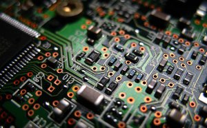
Solder Ball Residue Due to Excess Solder Paste and Improper Temperature
Solder balls or solder residue are often caused by excessive solder paste, an inappropriate temperature profile, or imprecise printing, which causes excess solder to form particles outside the solder joints and may lead to short circuits. Key control measures include using appropriate stencils and screens to regulate solder paste volume, optimizing uniform heating across all temperature zones of the reflow oven, and removing solder balls and residues through a dedicated post-soldering cleaning process to ensure a clean and reliable board surface.
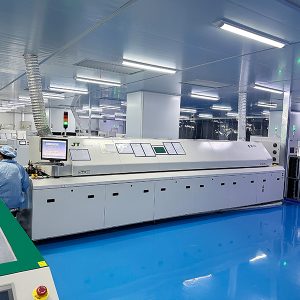
PCB Warpage and Deformation Caused by Materials and Heat Exposure
PCB warpage during reflow soldering can affect component placement and cause solder joint cracking. Causes include insufficient substrate heat resistance, uneven heating within the oven, and design flaws such as irregular shapes. Improvements can be made in three areas: selecting substrates with better heat resistance; reducing warpage during reflow through support structures and uniform temperature control; and enhancing warpage resistance during the design phase by adopting regular shapes and reinforced structures.
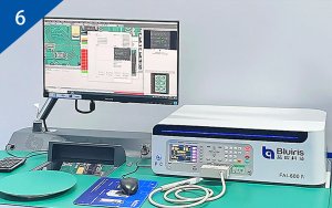
Electrical Malfunctions Point to Soldering and Design Defects
Electrical malfunctions manifest as open circuits, overcurrent, or signal interference, typically resulting from cold solder joints, critical component failures (such as shorted capacitors or open resistors), or improper layout. To address these issues, first use ICT (In-Circuit Testing) to comprehensively identify defective components and cold solder joints and repair them; strictly screen components during procurement and inspection to prevent defective materials from entering the production line; during the design phase, conduct signal integrity (SI) and power integrity (PI) analyses to mitigate interference and noise through proper layout.
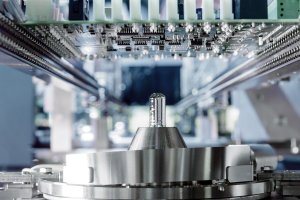
Optimizing Temperature Profiles Is the Core Method for Rework
Across the various issues mentioned above, the appropriateness of the reflow soldering temperature profile is critical to key processes such as soldering, solder ball formation, and warpage. Establishing temperature profiles customized to the characteristics of the PCB and components, combined with regular equipment calibration, can significantly improve first-pass yield and reduce the frequency of rework.
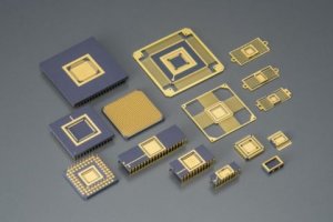
Standardized Operations and Incoming Material Screening Reduce Rework Rates
In addition to process parameters, standardized operator procedures and the quality of incoming materials also determine rework costs. Standardized training reduces human-induced damage, and when combined with strict incoming component inspection, this approach can minimize defect generation at the front end, achieving simultaneous improvements in rework efficiency and reliability.
