
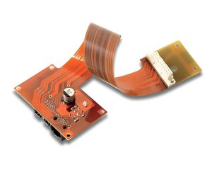
Flexible printed circuits (FPCs/flexible PCBs) are widely used in the consumer electronics, medical and automotive sectors due to their lightweight, thin and flexible nature. However, the assembly process for FPCs differs significantly from that of rigid boards. This article analyses the key technologies and considerations for FPC assembly in PCB Assembly
FPC Material and Structural Characteristics
FPC substrates are typically made of polyimide (PI) or polyester (PET), with copper foil thicknesses generally ranging from 12 to 35 μm.
Structural characteristics: lightweight and thin (0.1–0.2 mm), prone to deformation, a coefficient of thermal expansion different from that of rigid boards, and the use of stiffeners to enhance local rigidity.

Stiffener Design
FPCs require stiffeners to provide support in the component mounting areas.
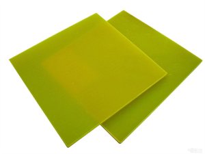
Stiffener materials: FR-4, PI, stainless steel or aluminium. Selection criteria: thickness requirements, heat dissipation needs and cost considerations.
Bonding methods: pressure-sensitive adhesive (PSA) or thermosetting adhesive. Stiffeners must be bonded prior to SMT.
SMT Process Adjustments
The flexibility of FPCs requires specialised fixtures and process parameters.
Fixture design: magnetic fixtures or vacuum-suction fixtures to ensure the FPC is held flat and secure.
SMT adjustments: Reduce placement pressure, optimise nozzle selection, and control FPC tension to prevent stretching and deformation.

Reflow soldering temperature profile
FPCs have low thermal capacity and heat up rapidly, so the temperature profile must be adjusted.
Key parameters: Reduce the preheat rate, shorten the dwell time in the high-temperature zone, use a support plate to prevent thermal deformation, and use nitrogen protection to minimise oxidation.

Connector crimping process
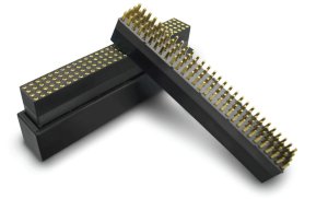
FPCs commonly use ZIF connectors or soldered connectors.
ZIF crimping: The thickness of the gold fingers must match the connector specifications (typically 0.2 mm or 0.3 mm); insertion depth and clamping force must be controlled.
Soldered connectors: A stiffener must cover the pad area to prevent FPC deformation during soldering.
Testing and Inspection
FPC testing must take its flexible characteristics into account.
Key test points: Bend testing (to verify the number of bend cycles), peel strength testing (adhesion of the stiffener), micro-section analysis (bonding between copper foil and substrate), and AOI inspection (parameters must be adjusted due to high reflectivity).
FPC assembly places higher demands on equipment and processes. Select a PCB assembly factory with experience in FPC assembly, and ensure thorough communication regarding stiffener and connector solutions during the design phase.
Frequently Asked Questions (FAQ)
Q1: How much more expensive is FPC assembly compared to rigid PCBs?
A: It is typically 20–40% more expensive, primarily due to: specialised fixtures, the stiffener lamination process, lower SMT efficiency (requiring more careful handling), and a higher defect rate. However, for space-constrained applications, the integration advantages of FPCs are irreplaceable.
Q2: Can components be mounted on both sides of an FPC?
A: Yes, but the process is complex. Double-sided mounting requires two reflow cycles, and FPCs are prone to warping. Typically, stepped stencils, localised support or two different temperature profiles are employed. The cost of double-sided mounting increases significantly.
Q3: How is the flex life of an FPC tested?
A: A dedicated flex life tester is used, in accordance with the IPC-6013 standard. Test parameters include: bend radius (typically R = 5–10 times the board thickness), bend angle (typically 180°), bending speed, and failure criteria (resistance change >10% or circuit break).
Q4: Can reinforcement panels be added at a later stage?
A: This is not recommended. Reinforcement panels must be laminated prior to SMT; otherwise, the FPC may deform during component placement. If design changes require additional reinforcement areas, the FPC will usually need to be remanufactured. It is essential to plan all reinforcement locations during the design phase.
Q5: How should the gold fingers on an FPC be protected?
A: The gold fingers are the key contact points between the FPC and the connector. Protective measures include: avoiding the gold fingers when applying a coverlay; applying a temporary protective film after SMT to prevent scratches; using anti-static bags and cardboard supports during packaging; and avoiding direct contact with the fingers.