

Power modules are the energy core of electronic systems, and their assembly quality directly affects system stability and efficiency. This article analyzes the key points of power module PCB assembly, with a particular focus on thermal management and current-carrying capacity design.
Key Components of Power Modules
Power circuits contain specialized components that are sensitive to assembly processes.
Major components: MOSFETs/IGBTs (switching devices, heat-sensitive), electrolytic capacitors (polarized components, lifespan affected by temperature), inductors/transformers (large size, high surface-mount pressure), and current-sensing resistors (low resistance, soldering quality affects accuracy).
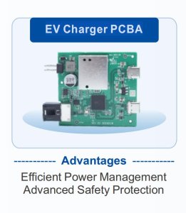
High-Current Trace Design
Power traces must carry currents in the ampere range, and conventional designs are prone to overheating.
Design Rules: Calculate trace width based on current density (typically 10 A/mm² of copper thickness); increase copper thickness (2 oz or 3 oz); use multiple parallel traces; and incorporate heat-dissipating via arrays.
Verification Methods: Infrared thermal imaging tests and temperature rise tests (under full-load operation).
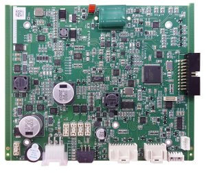
Selection of Thermal Management Solutions
Thermal management of power modules is critical to reliability.
Heat Dissipation Methods: Natural convection (copper fins + vias), forced air cooling (fan + heat sink), thermal pads/thermal grease (interface materials), and liquid cooling (for high-power applications).
Assembly Key Points: Ensure uniform contact pressure between the MOSFET and the heat sink; apply thermal grease in appropriate amounts (excessive amounts can actually insulate); and use insulating spacers (to prevent electrical short circuits).
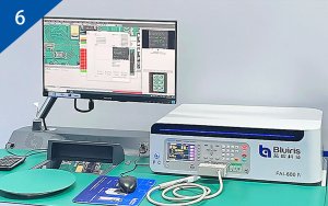
Current Detection and Calibration
Precision power supplies require accurate current detection.
Detection Methods: Shunt resistor (low cost but generates heat), Hall sensor (isolated but with limited accuracy).
Soldering Impact: The soldering quality of the shunt resistor (pad size, copper thickness, number of vias) directly affects the equivalent resistance value and temperature drift. A four-wire Kelvin connection is required to eliminate lead resistance.
EMI Suppression Design
Switching power supplies are a major source of EMI.
Suppression measures: Input filters (common-mode choke + X capacitor + Y capacitor), shielding (covering switching transistors and transformers), and optimized PCB layout (reducing loop area).
Assembly considerations: Ensure filter components are properly grounded, shielding is soldered continuously, and Y capacitors are positioned accurately.
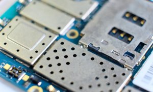
Aging and Full-Load Testing
Power supply modules must be verified for long-term stability.
Test items: Efficiency curves (at different loads), ripple and noise (measured with an oscilloscope), temperature rise (infrared thermal imager), and protection functions (overvoltage/overcurrent/overtemperature).
Test conditions: Input voltage range, load range, and ambient temperature.
Assembling power modules requires an understanding of the balance between electrical performance and thermal management. Select a PCB assembly factory with experience in power products and verify that it has high-current testing and thermal analysis capabilities.
Frequently Asked Questions (FAQ)
Q1: Why do MOSFETs in power modules tend to overheat?
A: The on-resistance (Rds(on)) of a MOSFET generates I²R losses, and switching losses are proportional to frequency. If the thermal design is inadequate (e.g., small heat sink, poor thermal grease, or poor contact), a junction temperature exceeding 150°C can lead to performance degradation or even burnout. Thermal resistance calculations and actual temperature rise testing are critical.
Q2: How is the lifespan of an electrolytic capacitor evaluated?
A: The lifespan of an electrolytic capacitor is strongly correlated with temperature, following the Arrhenius law: for every 10°C decrease in temperature, the lifespan doubles. For example, a capacitor rated at 105°C/2,000 hours will have a lifespan of approximately 32,000 hours in a 65°C environment. During assembly, avoid placing capacitors near heat sources (such as MOSFETs) and ensure proper ventilation.
Q3: Why does the soldering of shunt resistors affect accuracy?
A: Shunt resistors typically have a resistance of 1–100 mΩ, while the additional resistance from the copper pads and vias can reach 0.1–1 mΩ, significantly affecting accuracy. A four-wire Kelvin connection must be used: the current path and the sensing path are separated to eliminate the influence of lead resistance.
Q4: When should EMI testing be performed for power modules?
A: Conduct pre-compliance testing during the design phase using a near-field probe to locate radiation sources. Perform formal certification testing (CE/FCC/VCCI) before mass production. Ensure that filtering components and shielding covers are installed correctly during the assembly phase to avoid corrective actions later on.
Q5: How much thermal grease should be applied?
A: A thin layer (0.1–0.2 mm) is sufficient to cover the entire contact surface. Too much thermal grease can overflow and contaminate surrounding components, while too little can create air gaps that increase thermal resistance. It is recommended to use screen printing or metered dispensing to control the amount applied.
