
Industrial control PCBA
Control electronics built for continuous operation.
PCB assembly for automation, motion, monitoring and process-control equipment—reviewed around your approved design data, working environment and test plan.
Design-to-build priorities
Start with the conditions around the board.
Industrial electronics are defined as much by their enclosure and interfaces as by the circuit. The build package should make those constraints visible before material release.
ASSEMBLY REVIEWConnect electrical requirements to the physical build.
Thermal load
Identify heat sources, copper needs, airflow assumptions and component derating inputs.
Mechanical stress
Define vibration, connector retention, board support and enclosure-clearance requirements.
EMC & signal paths
Flag sensitive analog, power, communication and grounding areas for process review.
Contamination risk
Specify cleaning, conformal coating, masking and inspection criteria where required.
Representative board roles
Different control functions, one release discipline.
The exact process follows your board architecture, component mix, interfaces and acceptance plan.

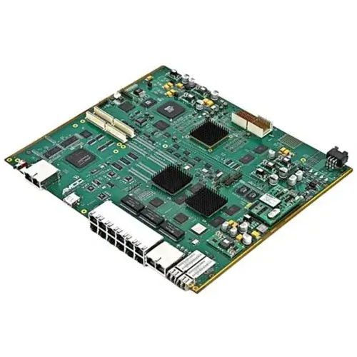
COMMUNICATION
Industrial gateways
Ethernet, fieldbus, isolation, service ports and controlled programming.
DATA ACQUISITION
Inspection and sensing
Dense signal paths, processing, memory and high-speed connectors.
MOTION & CONTROL
Machine controllers
Mixed I/O, power sections, relays, connectors and durable mounting.
Industrial IoT application scenes
Explore where connected control boards work.
Select a field to see how the operating environment changes the assembly focus. Each project is reviewed against its own design data and acceptance plan.
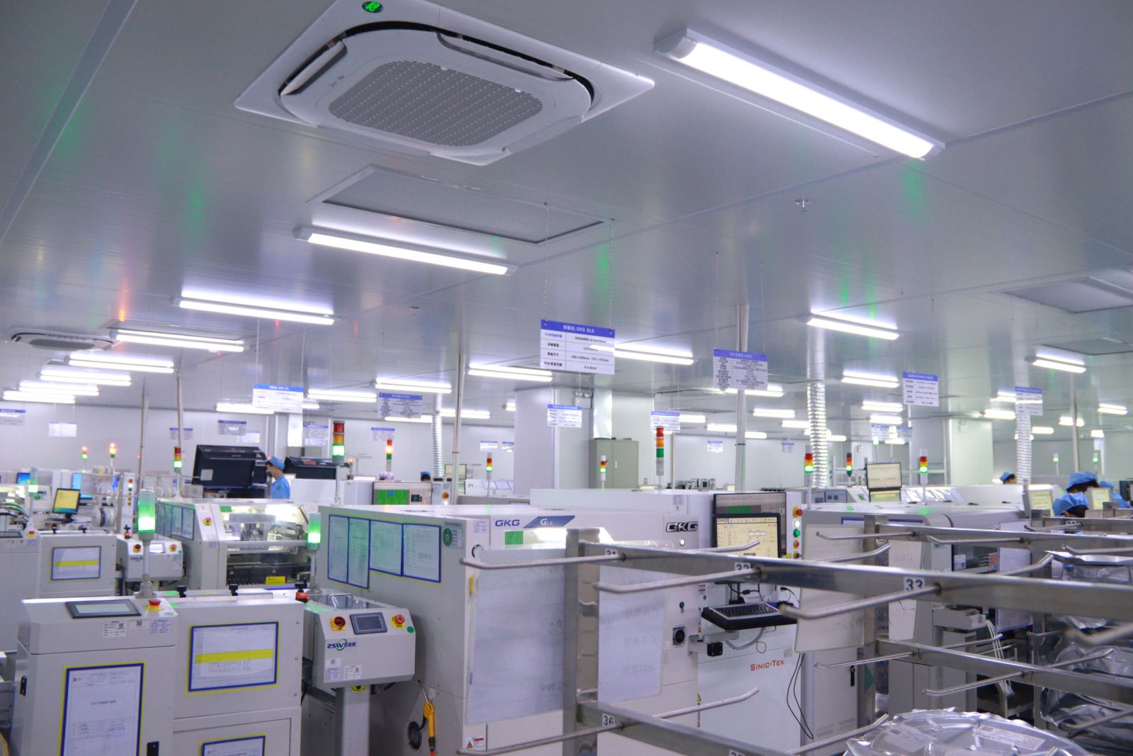
SMART FACTORY
Automation and motion control
Controllers, drives, sensors and machine interfaces need stable power, robust connectors and a test plan tied to real operating conditions.
Industrial control technical guide
The engineering details behind a durable build.
Industrial control PCBs support factory automation, process equipment, monitoring networks and other systems expected to operate consistently over long service periods.
The older page covered these technical topics in depth. They are retained here in a clearer structure so engineering teams can review the full context without losing the faster visual flow of the new page.
Quality & acceptanceMaterials & protectionThermal & EMCFabrication & assembly
01Quality standards and acceptance criteria
Industrial control assemblies frequently require clearly defined workmanship and inspection criteria. When specified by the customer, IPC-A-610 can be used to define electronic assembly acceptability and the applicable class should be confirmed in the build documentation.
Environmental test methods such as those in the IEC 60068-2 series, or industrial control-panel requirements such as UL 508A, may also affect the finished system. These requirements belong to the wider product and must be identified in the quotation package; PCB assembly alone does not establish end-product compliance.
02Materials for heat, moisture and chemical exposure
Material selection starts with the electrical, thermal and mechanical needs of the approved design. Base-material performance, copper construction, surface finish and component ratings should suit the expected temperature range and operating life.
Where dust, moisture or chemicals are present, the project may add cleaning controls, masking instructions and conformal coating. Coating material, coverage, thickness, cure method and inspection criteria must be specified because protection requirements vary by enclosure and application.
03Thermal management, EMC and signal integrity
Heat sources, copper areas, thermal vias, heat sinks and enclosure airflow should be reviewed together. Adequate spacing and a defined thermal path reduce hot spots and help avoid premature component or solder-joint stress.
Power switching, sensitive analog circuits, high-speed communication and grounding require deliberate separation and return-path control. Layout, shielding, filtering and connector placement should support the system EMC plan and preserve signal stability in a noisy industrial environment.
04Mechanical strength and vibration planning
Heavy connectors, relays, transformers and cable loads can place repeated stress on solder joints and mounting points. Board support, fastener locations, connector retention and enclosure clearances should therefore be visible in the assembly drawings.
For equipment exposed to vibration or shock, the project may require reinforced components, controlled adhesive application or additional inspection. Requirements must be agreed before production so materials and fixtures are included in the process plan.
05PCB fabrication, assembly and verification
PCB fabrication can include multilayer lamination, circuit imaging and etching, mechanical or laser drilling, copper plating, solder mask and final surface finish. Dimensional checks, registration control and electrical testing help verify the bare board before assembly.
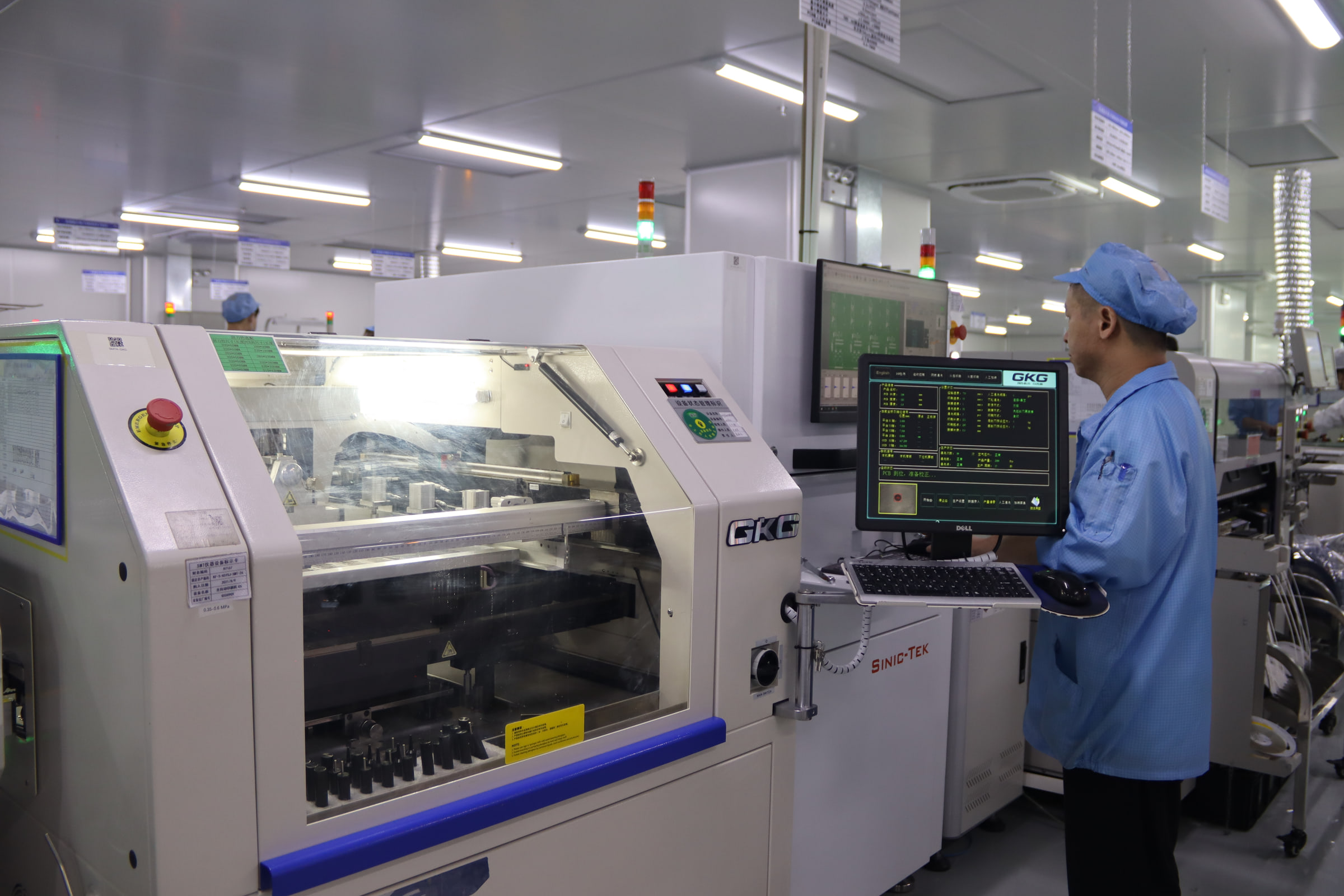
Assembly then follows the component mix: stencil printing, precision placement and reflow for SMT; selective, wave or controlled manual soldering for through-hole parts. SPI, AOI and X-ray can check hidden or visible joints, followed by programming, ICT or functional testing when the required fixtures, firmware and limits are available.
Manufacturing route
A visible path from files to accepted assembly.
Critical requirements are carried through material control, assembly, inspection and the agreed release records.
Package review
Gerber or ODB++, BOM, drawings, programming and change-control contacts.
Material control
Approved parts, substitutions, MSD handling and lot requirements.
Assembly
Stencil, placement, reflow, THT, selective or wave soldering as scoped.
Inspection
SPI, AOI, X-ray and workmanship review according to the assembly.
Test & release
Programming, ICT or functional test with agreed records and acceptance limits.
Build evidence
Records should match the project risk.
Tell us what your team needs at prototype, pilot and production stages so the quotation includes the right deliverables.
Approved build package
Revision-controlled fabrication data, BOM, AVL, drawings and special instructions.
Process checkpoints
Material traceability, programming, inspection and project-specific process records.
Acceptance results
Agreed test data, inspection evidence and release documentation for the build.
Project questions
What to define before quotation.
A clear operating environment and acceptance plan help us review the project quickly.
What files are required for an industrial control PCBA quote?
Start with Gerber or ODB++, drill and centroid data, BOM with approved parts, assembly drawings, quantities, delivery target, programming files and test requirements.
Can mixed SMT and through-hole assembly be included?
Yes. Share the connector, relay, transformer, press-fit and mechanical requirements so the route and fixtures can be reviewed.
Can conformal coating or cleaning be specified?
Yes, per project. Define material, masking, thickness or cleanliness criteria, cure conditions, inspection method and compatibility constraints.
Which tests can be included?
AOI, X-ray, ICT, programming and functional testing can be reviewed when fixtures, limits, firmware, simulators and acceptance criteria are available.
Start a project conversation
Send your industrial control PCBA requirements.
Share the board role, operating environment, quantity, target date and required records. We will confirm the information needed for quotation.
Engineering and sales review togetherPrototype through production supportMutual NDA available
Prefer email?
sales@keepbestpcba.com
Request an engineering review
Fields marked with * are required.