
Coordinate acquisition and calibration are core processes in SMT assembly, directly impacting placement accuracy and product quality. This article introduces methods such as machine coordinate calculation, laser positioning and vision recognition, and analyses four calibration techniques: reference point calibration, vision system calibration, laser alignment and automatic compensation. It also provides application recommendations tailored to both small- and large-scale production scenarios.

1.Basic Concepts of Coordinate Acquisition
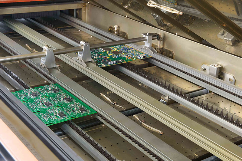
In SMT assembly, coordinate acquisition refers to the process of determining component placement positions through equipment and technical means. SMT placement machines typically require component coordinates based on PCB design files, such as Gerber files, and perform positional calibration during the actual manufacturing process. The coordinate acquisition process involves multiple factors, including machine origin setting, optical positioning technology, and the calculation of relative positions.
There are three common methods of coordinate acquisition. The machine’s built-in coordinate calculation and reading functions, which parse design files using internal algorithms. Laser positioning and optical systems, which utilise laser beams or optical sensors to determine physical positions. Vision systems and image recognition technology, which capture PCB feature points via cameras and calculate coordinates.
2.The Necessity of Coordinate Calibration

During the SMT placement process, coordinate errors may arise from various factors, such as machine accuracy, PCB warping, and environmental factors like temperature and humidity. It is therefore essential to calibrate machine coordinates regularly to ensure that every PCB is placed with precision.
3. Reference Point Calibration Method
Reference point calibration is one of the most common methods of coordinate calibration. By setting one or more reference points, automated equipment reads the actual position of these points and compares them with the positions specified in the design file. If a deviation is detected, the system automatically adjusts the machine’s coordinates to ensure subsequent placement accuracy. This method is typically suitable for scenarios where the equipment is relatively stable and the working environment is fairly consistent.
4.Vision System Calibration Method
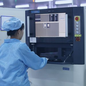
Modern SMT placement machines are often equipped with vision systems such as cameras, CCDs or CVI technology, which can scan feature points on the PCB—such as pads and character markings—in real time and compare them with the design coordinates to calibrate the placement machine’s positioning. The vision system calibration method offers high precision and is suitable for applications requiring high accuracy; it can significantly improve production efficiency and precision, particularly in mass production.
In terms of implementation techniques, real-time calibration can be achieved using clear PCB design files and image recognition software, making it adaptable to a variety of production environments. Regular cleaning of the camera lens and light source is key to ensuring accuracy.
5.Laser Alignment Calibration Method
Laser positioning systems project a laser beam onto the PCB surface to obtain the PCB’s coordinates in real time, which are then compared with the machine’s coordinate system. This method is commonly used in applications requiring high precision, particularly in high-speed placement or the production of large PCBs. Laser alignment technology not only enhances the accuracy of coordinate calibration but also reduces placement machine errors.
In terms of implementation techniques, when using laser alignment, it is essential to ensure that the laser light source and receiving equipment are properly calibrated to avoid deviations caused by equipment errors.
6.Automatic Compensation and Calibration Systems
Some advanced SMT placement machines are also equipped with automatic compensation systems, capable of dynamically compensating for coordinate deviations caused by environmental changes—such as temperature, humidity and machine wear—during the production process. These systems typically monitor and adjust placement coordinates in real time, ensuring that every production run achieves the expected precision.
In terms of implementation techniques, the effectiveness of automatic compensation systems is closely related to the stability and precision of the equipment itself. When selecting equipment, one should comprehensively consider the performance of its automatic calibration and compensation functions.
7. Analysis of Practical Application Scenarios
Mass production of standard electronic products: A combination of reference point calibration and vision system calibration is frequently employed. Reference points are used to establish the machine’s initial coordinates, whilst the vision system monitors and adjusts the placement position of each component in real time. This combined approach enhances production efficiency whilst maintaining precision.
Small-batch, high-precision customised products: Laser alignment calibration and automatic compensation systems are the ideal choice. Laser alignment technology ensures that the position of every PCB is precisely calibrated, whilst the automatic compensation system effectively addresses environmental fluctuations and machine wear that may occur during production.
Conclusion
The selection of a suitable solution for SMT coordinate acquisition and calibration must be based on production scale, precision requirements and environmental conditions. For high-volume production, a combination of reference points and vision-based calibration is recommended, whilst for small-batch, high-precision products, laser alignment coupled with automatic compensation is the preferred option. Mastering a variety of calibration techniques and applying them flexibly is key to achieving efficient and precise placement.