
Complete Gerber layer package
Include outline, copper, soldermask, silkscreen, solder paste and drill information so the board and assembly tooling can be reviewed together.
- Board outline
- Copper layers
- Soldermask
- Silkscreen
- Paste and drill data
PCB assembly required files
Combine your Gerber data, centroid file, BOM, assembly drawings and panel working Gerbers in one ZIP package. A complete input set helps engineering review manufacturing, sourcing and placement together.
You can start a discussion with incomplete files. Mark missing or inapplicable items explicitly; engineering should define what is required for the proposed scope.
On small screens, scroll the table horizontally.
| Review area | Information to prepare or request | Decision or record |
|---|---|---|
| Early consultation | Product purpose, stage, quantity and the unresolved question | Describe missing files without pretending they are ready |
| Quotation review | Board revision, BOM, supply model, quantity and acceptance scope | Add placement, drawings and test information as available |
| Production release | Approved data, alternatives, fixtures/firmware and final acceptance criteria | Panel data is applicable only when the agreed build uses a panel |
Interactive preflight check
Check each item as you prepare the ZIP. This local checklist stays in your browser and does not upload any data.
Start with the approved design revision.
Five-file package guide
Choose a file type to see why engineering needs it, which information it should contain and where it is used on the factory floor.
Include outline, copper, soldermask, silkscreen, solder paste and drill information so the board and assembly tooling can be reviewed together.
Include outline, copper, soldermask, silkscreen, solder paste and drill information so the board and assembly tooling can be reviewed together.
Provide component locations, rotations and reference designators so placement programs can be prepared and checked against the BOM.
A structured BOM helps engineering and purchasing align quantity, manufacturer part number, description, technology and package for every fitted component.
Drawings communicate polarity, component orientation, fitted or not-fitted positions, mechanical details and any special assembly instructions.
When the PCB house has panelized the boards, provide its working Gerbers so the actual production panel can be used to prepare the SMT stencil.
Illustrative layer stack. The drawing is a file guide, not a manufactured board photograph.
01 · Gerber files
Gerbers translate your layout into manufacturing images. Clear naming and a complete layer set reduce the risk of interpreting the wrong side, finish or revision.
03 · Bill of materials
Excel is the preferred working format. The more precise the manufacturer part number and description, the fewer sourcing assumptions are required.
From spreadsheet to controlled material
Part identity must remain aligned from quotation through incoming inspection and production release.
Learn about PCB BOMsThese six data groups help engineering and purchasing prepare an accurate component review.
02 + 04 · Placement and build guidance
The centroid file and assembly drawing answer different questions. Providing both helps cross-check component identity, position, orientation and special build requirements.
Use consistent units and clearly identify top and bottom placement sides.
Include drawings when they clarify do-not-fit positions, connectors, mechanical hardware or customer-specific notes.
05 · Working Gerber files
If your PCB supplier panelizes the boards, include the working Gerbers generated by that PCB house. These reflect the actual panel used to fabricate the SMT stencil.
A cleaner engineering handoff
A complete package lets engineering connect design data, component information and assembly requirements before quotation and release.

Keep Gerber, centroid, BOM, drawings and panel data on the same approved revision.
State quantity, target schedule, sourcing responsibility and any test or programming needs.
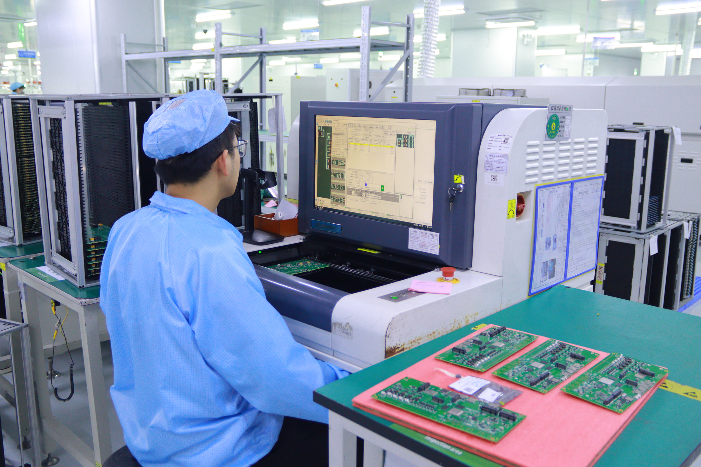
Manufacturing, placement, component and inspection inputs are reviewed together for quotation.
Required files FAQ
Clear file names, matching revisions and complete manufacturing data help prevent unnecessary clarification cycles.
Yes. A single ZIP keeps the manufacturing and assembly inputs together. Use clear file names and keep every file on the same approved revision.
Include component X and Y locations, rotation, reference designators and preferably top or bottom placement side.
Excel is preferred because structured rows and columns are easier to review, source and compare. Include exact manufacturer part numbers wherever possible.
Include them when available. They are particularly useful for polarity, orientation, do-not-fit parts, connectors and mechanical instructions.
The final working Gerbers from the PCB house represent the production panel and help fabricate the SMT stencil against the correct layout, fiducials and rails.
Prepare your review package
Include project quantity, assembly type, testing needs and the target schedule. The team can then review the manufacturing and quotation inputs together.