
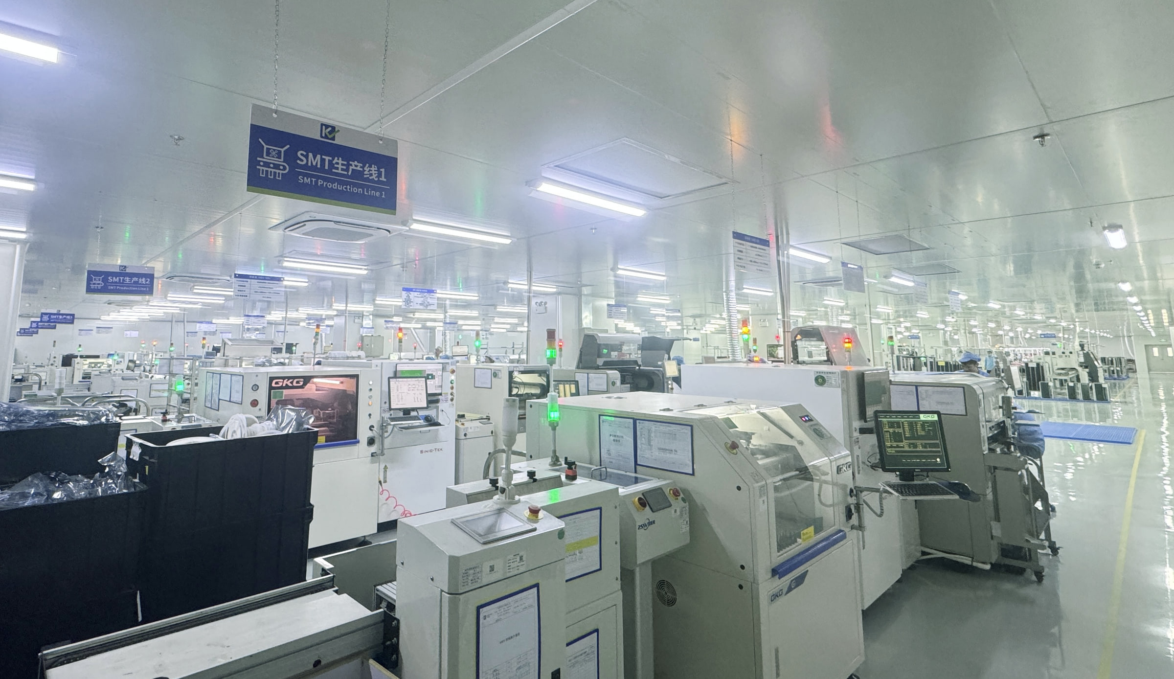
China & Thailand PCBA manufacturing support
SMT production line

Placement, reflow and inspection

SMT Assembly Planned Around Your Board and Packages

Align BOM, placement data, component orientation and the soldering route before the build. Define first article checks and the inspection needed for visible and hidden solder joints.
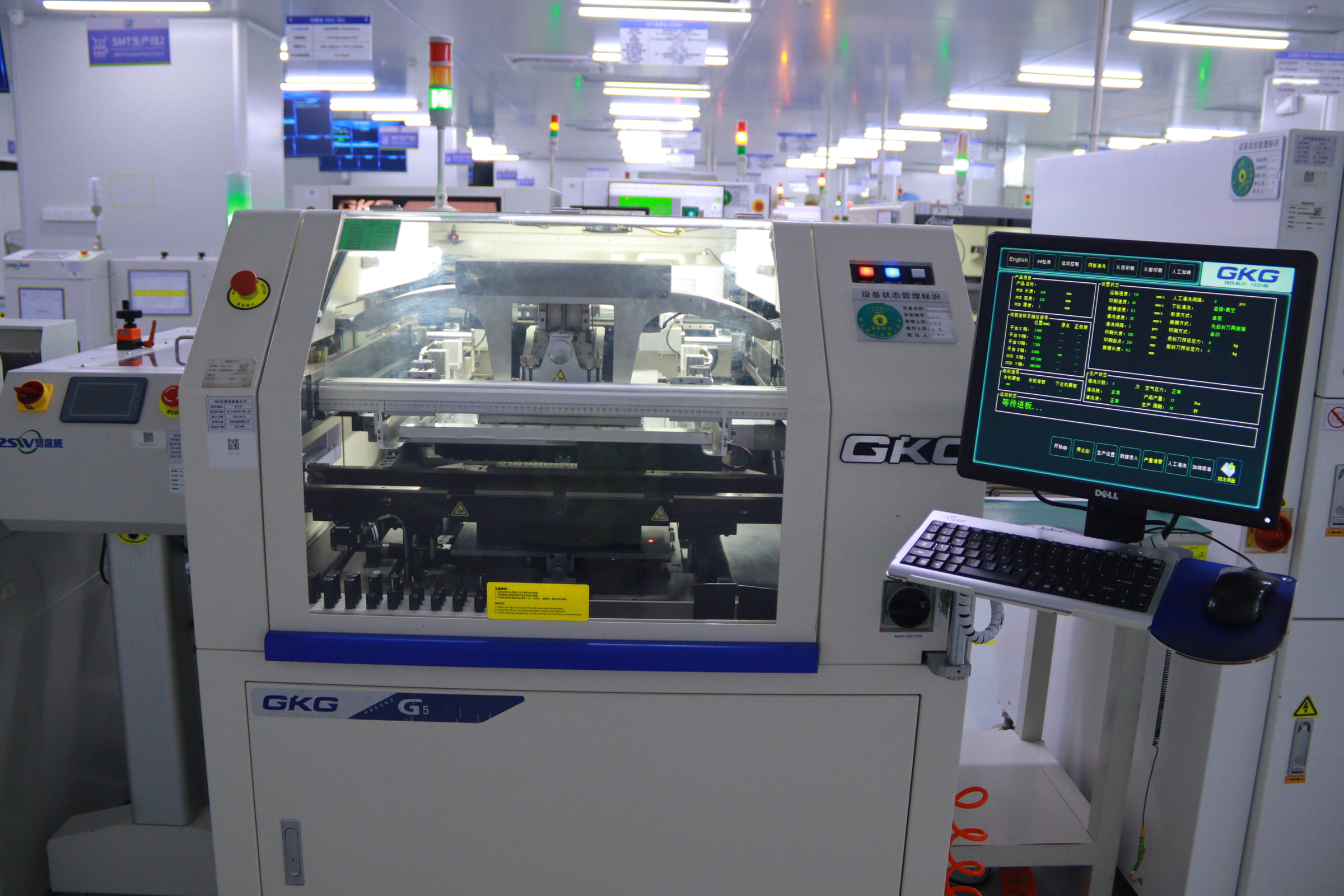
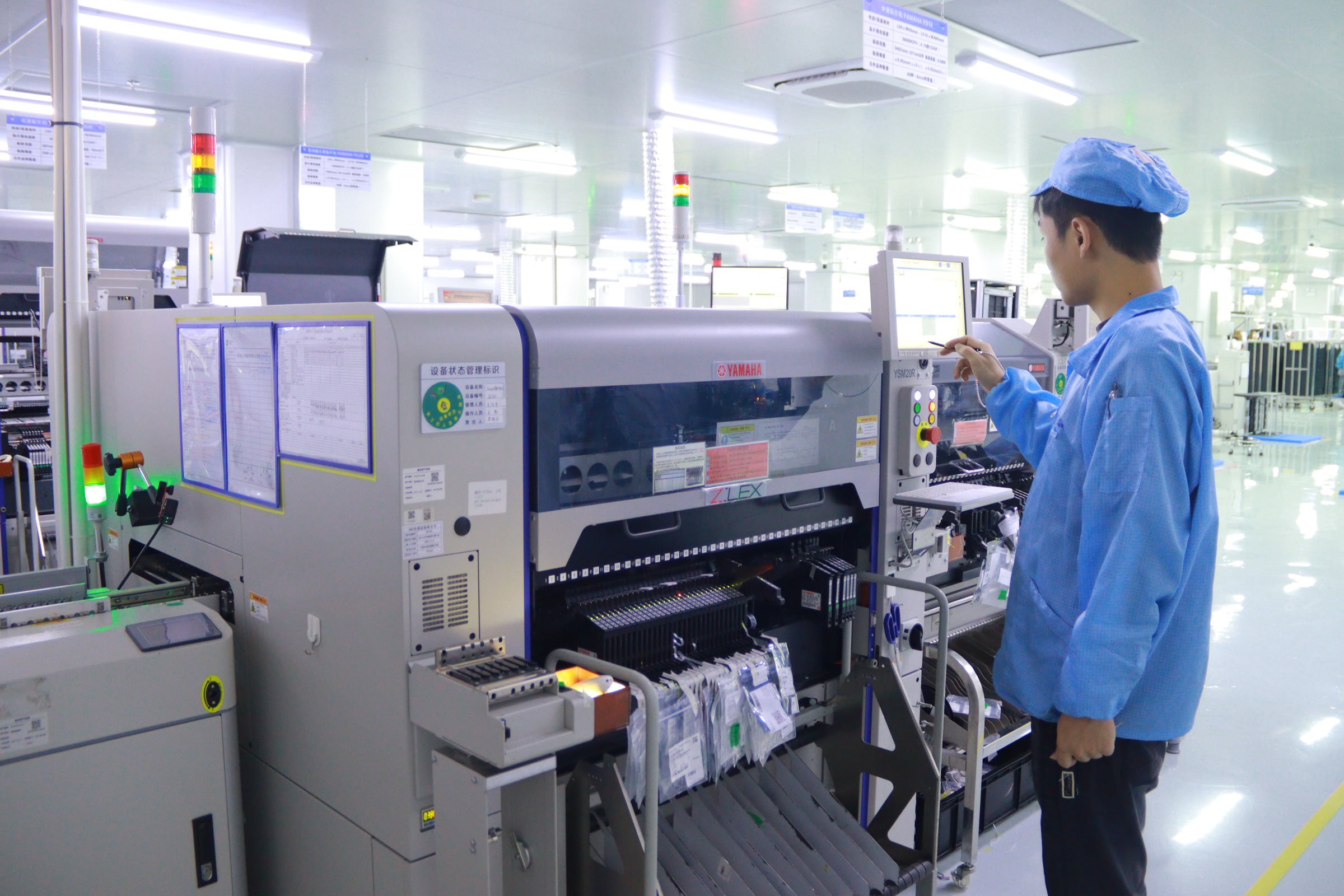
KeepBest company photograph

Printing, placement, reflow and inspection

Connect printing, placement, reflow and inspection to the component mix and board design. Review where solder paste inspection, optical checks or X-ray inspection support the agreed acceptance plan.

First-article review example · Use these fields to define the requested review. Example entries are illustrative; the order confirms the accepted scope and records.

Compare columns · swipe or scroll on smaller screens

First-article fieldYour released inputExample disposition before continuation
Reference / packageBOM MPN, land pattern and placement referenceVerify the same device and footprint; resolve any mismatch.
Rotation / polarityCentroid convention and assembly drawingRecord the affected RefDes and image / observation; customer approves correction.
Release statusBOM, placement and drawing revisionAccepted / awaiting decision; link the approved response to the revised file set.
Detailed engineering considerations

An SMT build depends on the fit between component packages, PCB land patterns, solder paste and the thermal process. KeepBest reviews these inputs with your BOM and placement files to plan the assembly route. For prototype, NPI or repeat orders, define inspection needs and special handling requirements before the design reaches the production line.

Printing

KeepBest company photograph · visible production reference

Placement

KeepBest company photograph · visible production reference

Reflow route

KeepBest company photograph · visible production reference

Optical inspection

KeepBest company photograph · visible production reference

Prepare the paste and component data

Review stencil features, board support, rotations and component identity together.

Solder paste and stencil

Review aperture design, land patterns and paste requirements against the actual component packages. Fiducials, panel support and access around dense areas influence how the board is prepared for printing and placement.

Placement and component data

Match reference designators, rotations and package information between the BOM and pick-and-place file. Identify polarity, unusual components and customer-specified handling instructions before the placement program and first article are reviewed.

Confirm the thermal route and joint inspection

The assembly sequence and checks follow the actual materials and package risks.

Reflow and material compatibility

Assess the temperature limits of components, laminate and finish alongside the soldering requirements. Double-sided assemblies and thermally sensitive devices need a reviewed sequence rather than an assumed standard thermal process.

Inspection for visible and hidden joints

Use the inspection plan to address paste printing, component presence, orientation and solder workmanship. Hidden-joint packages may need an additional X-ray review, with criteria defined for the specific design.

Moisture and storage requirements

Identify components that require controlled storage or handling using their packaging and manufacturer information. Agree incoming condition, exposure history and preparation requirements so the build starts with suitable material.

Inputs, decisions & outputs

From package review to inspected SMT assemblies

  1. 01

    Check package and file consistency

    Compare the BOM, board data and placement information for package, reference and orientation differences. Confirm do-not-fit components and sensitive areas before assembly preparation uses the released manufacturing data.

  2. 02

    Prepare the printing and placement route

    Review stencil, paste, fiducials, panel support and component presentation for the design. The first article review uses these agreed inputs to identify issues before the intended build proceeds.

  3. 03

    Review the soldering sequence

    Assess the populated sides and component temperature constraints against the selected process. Any exceptions, special handling or changes to the approved design return to engineering and the customer for confirmation.

  4. 04

    Inspect and complete the build

    Apply the agreed paste, optical and additional inspection checks at the appropriate stages. Programming and functional testing follow their own approved specifications, with disposition recorded for units that need further review.

Your project

Prepare the SMT release files

Select the items you want to carry into the project brief.

Before release

Questions about surface mount assembly

Can SMT assembly include BGA or QFN packages?

Provide the exact part numbers, package details and board files for feasibility and inspection review. The package geometry and hidden joints determine the assembly and inspection requirements that engineering needs to confirm.

Which files control component rotation?

Provide pick-and-place data and an assembly drawing with polarity and orientation references. Package libraries and coordinate conventions can differ, so first article review should confirm the intended physical orientation on the board.

Does AOI verify all solder joints?

AOI reviews visible assembly features. Hidden connections under packages may need X-ray or another agreed method. Neither visual method replaces an electrical or functional test required by the product acceptance specification.

What changes for a double-sided SMT board?

The process sequence must consider component retention, thermal exposure, support and any later through-hole operations. Mark both populated sides and relevant part restrictions so engineering can review the complete route.

Can the project include through-hole parts too?

Yes, a mixed technology route can combine SMT and THT. Provide insertion and soldering requirements for the through-hole components so their processing and inspection fit the completed SMT assembly.

Placement, reflow and inspection

Prepare your project brief.

Tell us what you are building and what you need reviewed. Include the current revision, quantities and any open questions. The project scope and acceptance criteria are agreed from your requirements.

Review the required files →

Submit your details and files for project review. A saved reference confirms receipt; notification delivery is tracked separately.

Send a project enquiry

* Required
    ZIP, Gerber/drill, CSV, XLSX or PDF · up to 10 files, 10 MB each, 20 MB total.
    Files are stored privately for project review.

    Get A Quote

    Fill in your requirement information and upload Gerber and BOM files, we will give you a quote within 24 hours.

    Get A quote

    Fill in your requirement information and upload Gerber and BOM files, we will give you a quote within 24 hours.